Heat exchanger assembly utilizing grommets and integral cast tanks

a technology of heat exchangers and grommets, applied in indirect heat exchangers, machines/engines, lighting and heating apparatus, etc., can solve the problems of increasing the length of tubes, increasing the mechanical stress on the tanks and the associated headers, and increasing the stress on the tube-to-header joints

Inactive Publication Date: 2001-12-18
VISTA PRO AUTOMOTIVE
View PDF29 Cites 27 Cited by
  • Summary
  • Abstract
  • Description
  • Claims
  • Application Information

AI Technical Summary

Problems solved by technology

In use, heat from the hot liquid or air within generally causes the tubes to expand and grow in length due to thermal expansion.
Since the tanks or manifolds are fixed with respect to each other by the unit framework or structure, the growth in length of tubes places high mechanical stresses on the tanks and the associated headers, particularly in the area of the joints between the tubes and headers.
In addition, the pressure of the hot liquid or hot air within the heat exchanger tends to distort the tanks or manifolds and headers, creating further stresses on the tube-to-header joints.
The combination of stress resulting from thermal expansion and internal pressure can result in early failure of heat exchangers.
Cracks in the joints between the tubes and the headers are the most common mode of failure.
While this has been an extremely effective design under typical operating conditions for locomotives, it is expensive to produce.
However, considerable force was required to insert all

Method used


Image

  • Heat exchanger assembly utilizing grommets and integral cast tanks
  • Heat exchanger assembly utilizing grommets and integral cast tanks
  • Heat exchanger assembly utilizing grommets and integral cast tanks

Examples


Embodiment Construction

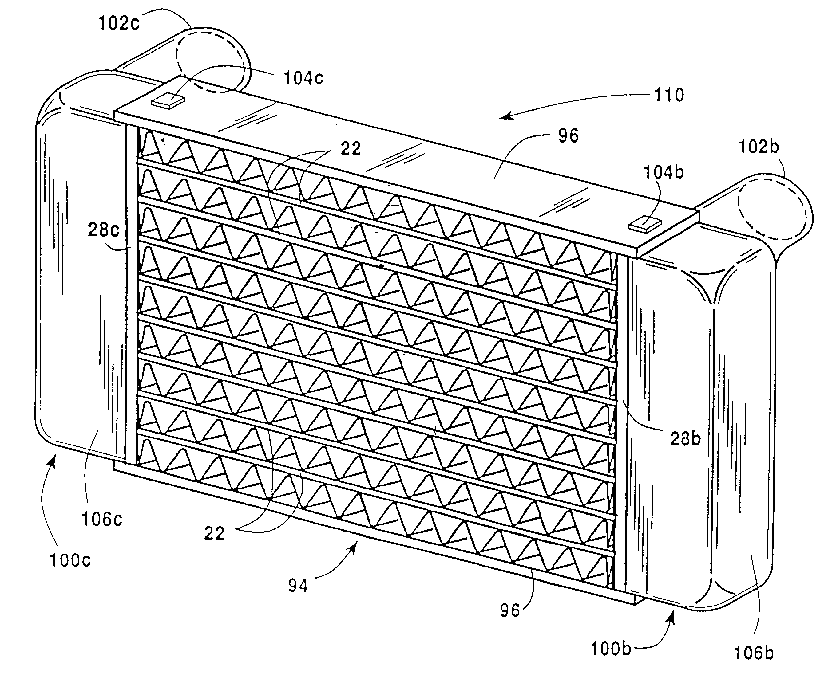
This invention is directed primarily toward an air-to-air heat exchanger used as a charge air cooler, or intercooler, for turbocharged or supercharged engines. However, it may also be utilized in any other type of heat exchanger, for example, those discussed in the background of the invention, such as radiators, oil coolers and the like. The present invention provides a heat exchanger which has an integral cast combined header and tank with openings in the header portion and a resilient tube-to-header portion joint to minimize tube-to-header stresses due to a combination of a thermal expansion of the tubes and internal pressure in the tanks. Preferably oval tubes are utilized for close tube spacing for optimum heat transfer performance of the core, although other tube shapes and cross-sections may be utilized.

In accordance with the present invention, the heat exchanger employs a combined cast header and tank having a header portion integral with a tank portion. As shown in FIGS. 5-7...


PUM

PropertyMeasurementUnit
Resilienceaaaaaaaaaa

Abstract

A heat exchanger comprises an as-cast combined header and tank having a header portion integral with a tank portion. The cast header and tank combination has a plurality of openings originally cast in the header portion of the combination and at least one opening originally cast in the tank portion of the combination for passage of coolant into or out of the cast header and tank combination. Tubes are received in and extends through the header portion openings, and resilient grommets seal the tubes to the header portion to prevent leakage around the tubes. In making the heat exchanger, there is provided an inner mold section and outer mold section corresponding respectively to the interior and exterior configurations of a desired combined header and tank having a header portion integral with a tank portion. The inner mold and outer mold sections are connected through the header and tank portion openings to support the inner mold section within the outer mold section and create a space therebetween corresponding to the configuration of the combined header and tank. The space is filled with molten metal and solidified to create the combined cast header and tank having the header portion integral with a tank portion. The outer mold section is removed and the inner mold section is removed from inside the cast header and tank through an opening in the header portion and/or through an opening in the tank portion. Following removal of the mold portions, the method may include inserting a tube from a heat exchanger core into an opening in the cast header portion and securing the tube therein.

Description

DESCRIPTION1. Technical FieldThis invention relates to heat exchangers and, more particularly, to motor vehicle heat exchangers utilizing grommets in the tube-to-header joints.2. Background ArtHeat exchangers, particularly those utilized in motor vehicles, may be liquid-to-air heat exchangers, (e.g., radiators for engine coolant, air conditioning condensers and evaporators, and oil coolers) or may be air-to-air heat exchangers (e.g. charge air coolers). Liquid-to-air and air-to-air heat exchangers are typically composed of an inlet tank or manifold, an outlet tank or manifold, and a large number of tubes extending between the tanks or manifolds which carry the fluid to be cooled. Headers are normally provided on the tanks for mechanical attachment and fluid connection of the tubes. Fins attached to the tubes transfer heat between the liquid or gas inside the tubes and the ambient atmosphere outside. A mechanical framework or structure is usually included to provide structural streng...

Claims


Application Information

Patent Timeline
IPC IPC(8): B23P15/26F28F9/02F28F1/12F28F9/04F28F21/08F28F21/00F28F9/14F28D1/053F28D1/04F28F11/00
CPCB23P15/26F02B29/0456F28D1/05366F28F1/126F28F9/02F28F21/084F28F21/085F28F9/14Y10T29/49389Y02T10/146Y10T29/49417Y10T29/49664Y02T10/12
Inventor LAMBERT, MARCOKOLB, MICHAEL J.
Owner VISTA PRO AUTOMOTIVE
Why Eureka
Try Eureka