Device and method for determining the concentration of a substrate

Inactive Publication Date: 2002-01-22
PHC HLDG CORP
View PDF9 Cites 140 Cited by
  • Summary
  • Abstract
  • Description
  • Claims
  • Application Information

AI Technical Summary

Benefits of technology

Subsequently, a potential for oxidizing the above-mentioned reduced form electron mediator is applied onto the working electrode 7 with reference to the counter electrode 6 to measure a current value between the counter electrode 6 and the working electrode 7. This current is derived from the oxidation reactions of the reduced form electron mediator and the preexisting interfering substance ascorbic acid. In other words, the ascorbic acid produces a positive error in the measurement result. The above-mentioned current value between the counter electrode 6 an

Problems solved by technology

However, all of those methods have poor accuracy because of poor specificity to sugars.
Of those methods, polarimetry is simple in manipulation but is largely affected by the temperature during operation.
Therefore, polarimetry is not a suitable method for ordinary people to carry out determination of sugars at home or elsewhere in a simplified manner.
As can be speculated from the reaction process, this method has a drawback that the measurement result is largely affected by the oxygen concentration in the sample solution.
Furthermore, measurement is impossib

Method used


Image

  • Device and method for determining the concentration of a substrate
  • Device and method for determining the concentration of a substrate
  • Device and method for determining the concentration of a substrate

Examples


example 2

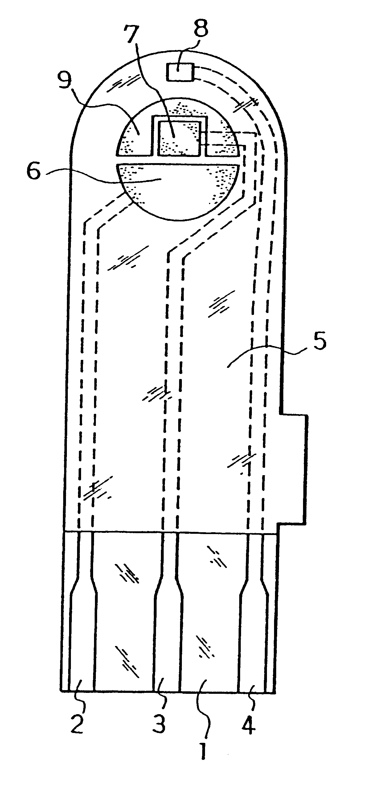
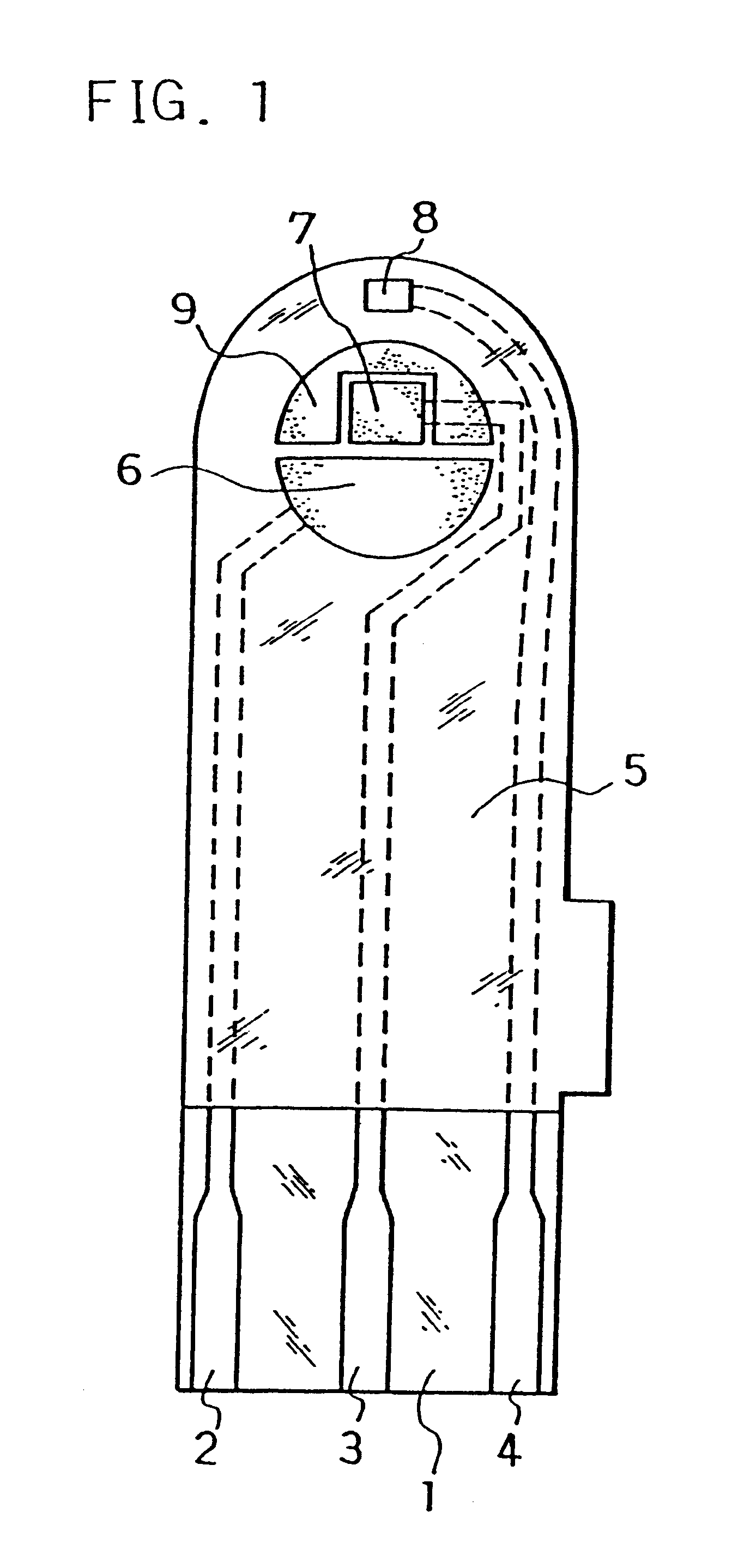
The electrodes 6, 7, 8 and carbon layer 9 were formed on the base plate 1 in the same manner as in Example 1. Next, an aqueous CMC solution was dropped on the counter electrode 6, working electrode 7 and carbon layer 9 while omitting the third electrode 8 and dried to form the CMC layer, on which an aqueous solution containing GOD as an enzyme and potassium ferricyanide as an electron mediator was further dropped and dried to form the reaction layer.

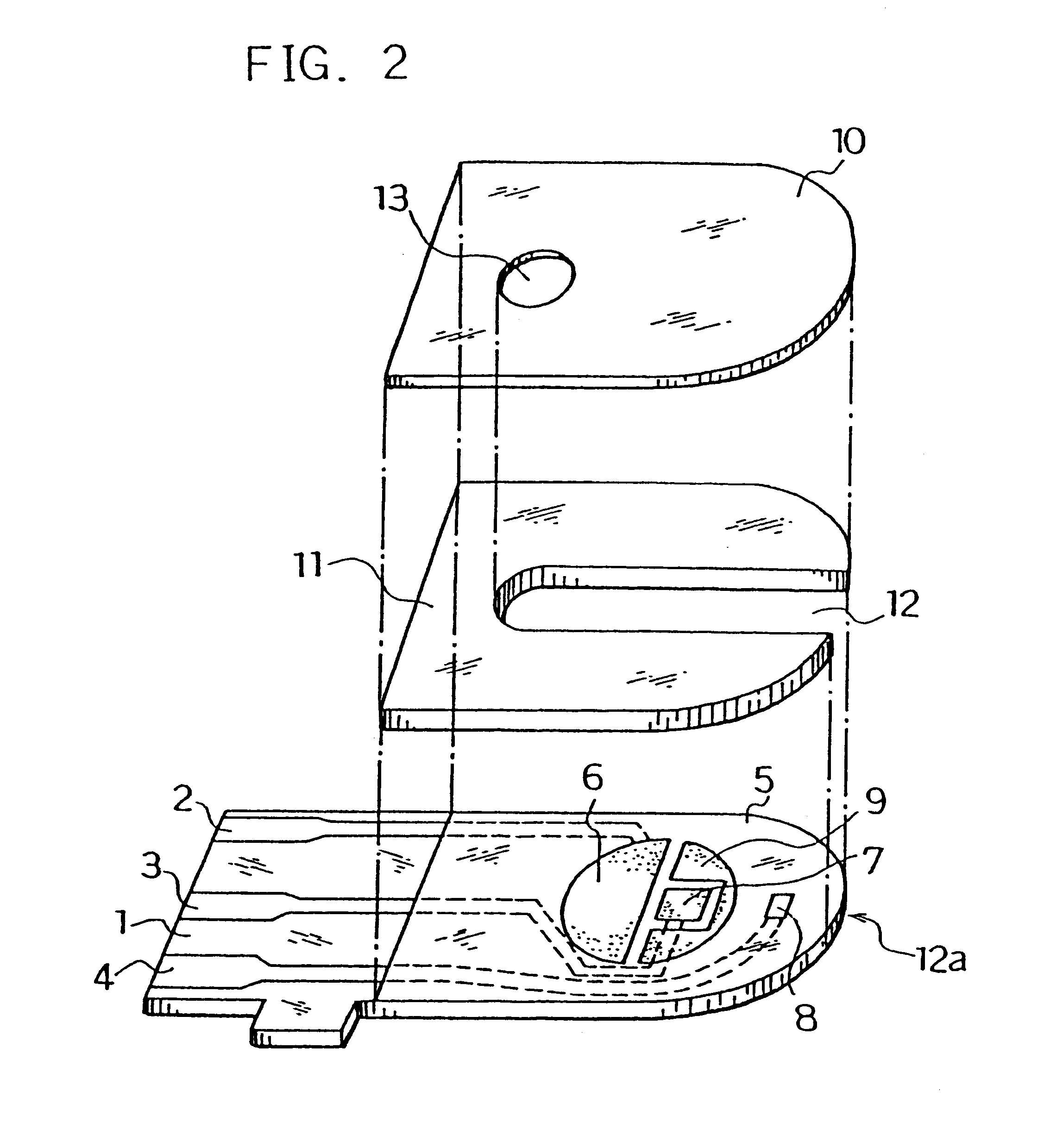
Next, for further smoothing supply of the sample solution to the reaction layer, an organic solvent solution of lecithin, such as toluene solution, for example, was spread from the sample solution supply port toward the reaction layer and dried to form a lecithin layer on the reaction layer. Next, the cover 10 and the spacer 11 were bonded to the base plate 1 in a positional relationship as shown by the dotted chain line in FIG. 2 to form a glucose sensor.

The sensor was set on a measurement device and a potential of 500 mV was applied on...

example 3

A glucose sensor was produced in the same manner as in Example 2.

The sensor was set on a measurement device and a potential of 500 mV was applied onto the third electrode 8 with reference to the counter electrode 6. With the potential kept applied, an aqueous glucose solution containing ascorbic acid as an interfering substance was supplied through the sample solution supply port 12a at 3 .mu.l as a sample solution. The sample solution reached the air vent 13 by passing through the sample solution supply pathway and dissolved the reaction layer on the electrode system.

Upon supply of the sample solution, a liquid supply detecting system started to operate based on an electrical change between the counter electrode 6 and the third electrode 8 of the electrode system, which then started a measurement timer. At that time, the potential application is being continued between the counter electrode 6 and the third electrode 8, and after a lapse of a certain time from the detection of suppl...

example 4

In the same manner as in Example 2, the reaction layer was formed on the counter electrode 6, working electrode 7 and carbon layer 9 while omitting the third electrode 8.

Next, an organic solvent solution of lecithin such as toluene solution, for example, was spread on a groove formed on the cover member for forming the sample solution supply pathway and dried, thereby to form the lecithin layer for the purpose of still more smoothing supply of the sample solution to the reaction layer. Then, the cover 10 and the spacer 11 were bonded to the base plate 1 in a positional relationship as shown by the dotted chain line in FIG. 2, which gave a glucose sensor.

Positioning the lecithin layer from the reaction layer over the third electrode 8 may sometimes increase variations in sensor response characteristics due to a change of the surface of the third electrode by the lecithin layer. Positioning the lecithin layer on the cover member side as shown above resulted in a decrease in such varia...


PUM


Abstract

A method for determining the concentration of a substrate in a sample solution using an electrode system comprising a working electrode, a counter electrode, and a reaction layer which contains at least an oxidoreductase and an electron mediator and is formed on the electrode system to electrochemically measure a reduced amount of the electron mediator resulting from enzyme reaction in the reaction layer, wherein a third electrode is formed as an interfering substance detecting electrode. A current flowing between the counter electrode and the third electrode is measured which is taken as a positive error. Subsequently, voltage application between the counter electrode and the third electrode is released and a voltage for oxidizing the reduced form electron mediator is applied between the working electrode and the counter electrode to measure a current flowing between the two electrodes.

Description

The present invention relates to a method for performing rapid and high accuracy determination of a substrate in a sample in a simplified manner.As the method for quantitative analysis of sugars such as sucrose and glucose, polarimetry, colorimetry, reductiometry, and methods using a variety of chromatography have been developed. However, all of those methods have poor accuracy because of poor specificity to sugars. Of those methods, polarimetry is simple in manipulation but is largely affected by the temperature during operation. Therefore, polarimetry is not a suitable method for ordinary people to carry out determination of sugars at home or elsewhere in a simplified manner.Apropos, various types of biosensor have been developed recently which use specific catalytic actions of enzymes.In the following, a method of glucose determination will be described as one example of the method of substrate determination in a sample solution. A generally known electrochemical method of glucos...

Claims


Application Information

Patent Timeline
IPC IPC(8): C12Q1/00
CPCC12Q1/004
Inventor IKEDA, SHINYOSHIOKA, TOSHIHIKONANKAI, SHIRO
Owner PHC HLDG CORP
Why Eureka
Try Eureka