Method and apparatus for imaging artefact reduction

a technology of artefact reduction and imaging, applied in the field of image processing, can solve the problems of phase shift that is a more complicated function, significant compromise of spatial resolution and image quality, and degradation of images that can obscur

Inactive Publication Date: 2002-01-22
NANOGEN RECOGNOMICS BMBH +1
View PDF6 Cites 94 Cited by
  • Summary
  • Abstract
  • Description
  • Claims
  • Application Information

AI Technical Summary

Problems solved by technology

In the extreme case, single shot echo planar imaging (EPI) techniques cover the whole of two dimensional k-space in a single acquisition lasting less than 100 ms, although spatial resolution and image quality may be significantly compromised.
Patient movement during the acquisition of MRI images results in degradation of the images that can obscure the clinically relevant information.
Movement leads to phase errors between lines of k-space, which in the resulting image appear as blurring and ghosting along the phase encode direction.
These phase errors can result from translations and rotations.
Rotations in the spatial domain are also rotations in k-space, and result in a phase shift that is a more complicated function of position.
A side effect is that the images are also sensitive to bulk motion on the same scale.
The impact of different types of motion on the resulting images is well understood, but clinically usable retrospective motion correction techniques are not yet available.
Existing algorithms tend to correct only for one dimensional motion, or they require exotic image acquisition strategies that are not generally applicable.
A possible solution to this is to acquire spiral readouts, all of which sample a range of spatial frequencies as described by Khadem et al. in Proc. Soc. Magn. Reson., 1994, page 346, but this is impractical on the majority of MRI hardware.
This technique cannot correct for continuous movement during acquisition, and would appear to require considerable user interaction.
In general, a mask image as required by this algorithm, may not be available, or may be out of registration with the images that need correction, and thus inaccurate.
It is likely that to be effective, this technique requires the image to be sub-divided into regions. where the ghosts do not overlap either each other or the main body of the image and therefore its applicability is limited.
It does not correct for artefacts due to motion.
Correction for motion artefacts is more complex because motion affects the focus in all regions and in general there are six degrees of freedom rather than one for field inhomogeneities.

Method used


Image

  • Method and apparatus for imaging artefact reduction
  • Method and apparatus for imaging artefact reduction
  • Method and apparatus for imaging artefact reduction

Examples


Embodiment Construction

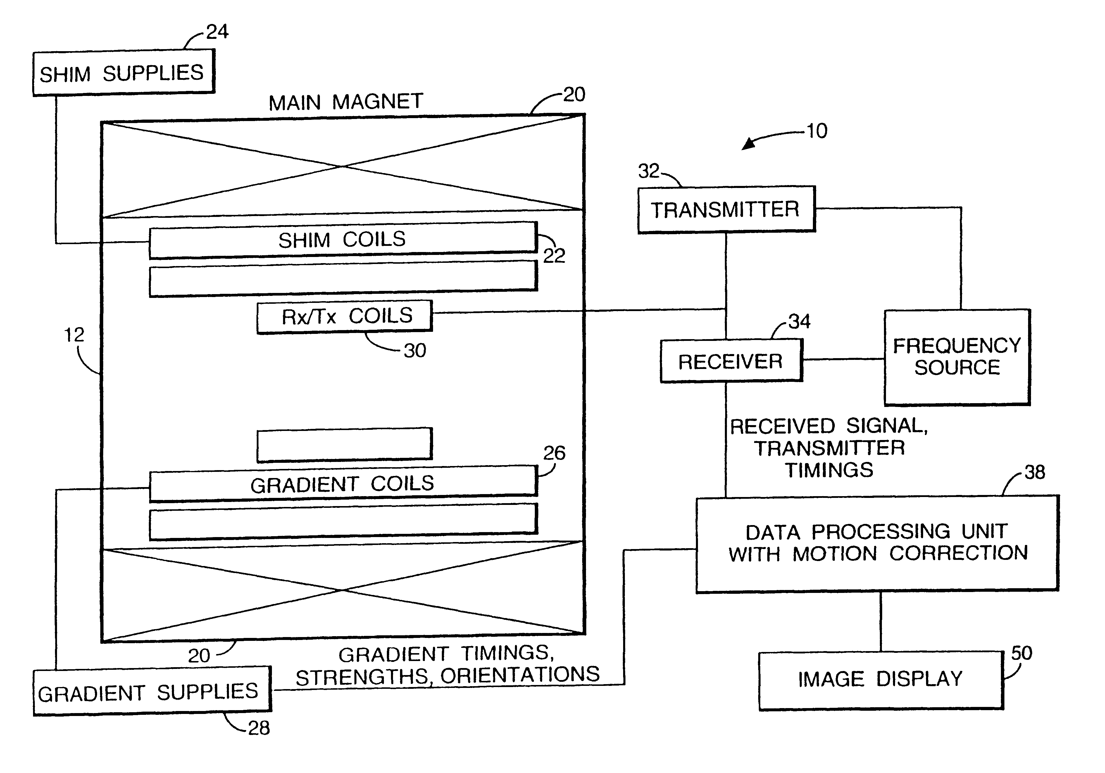
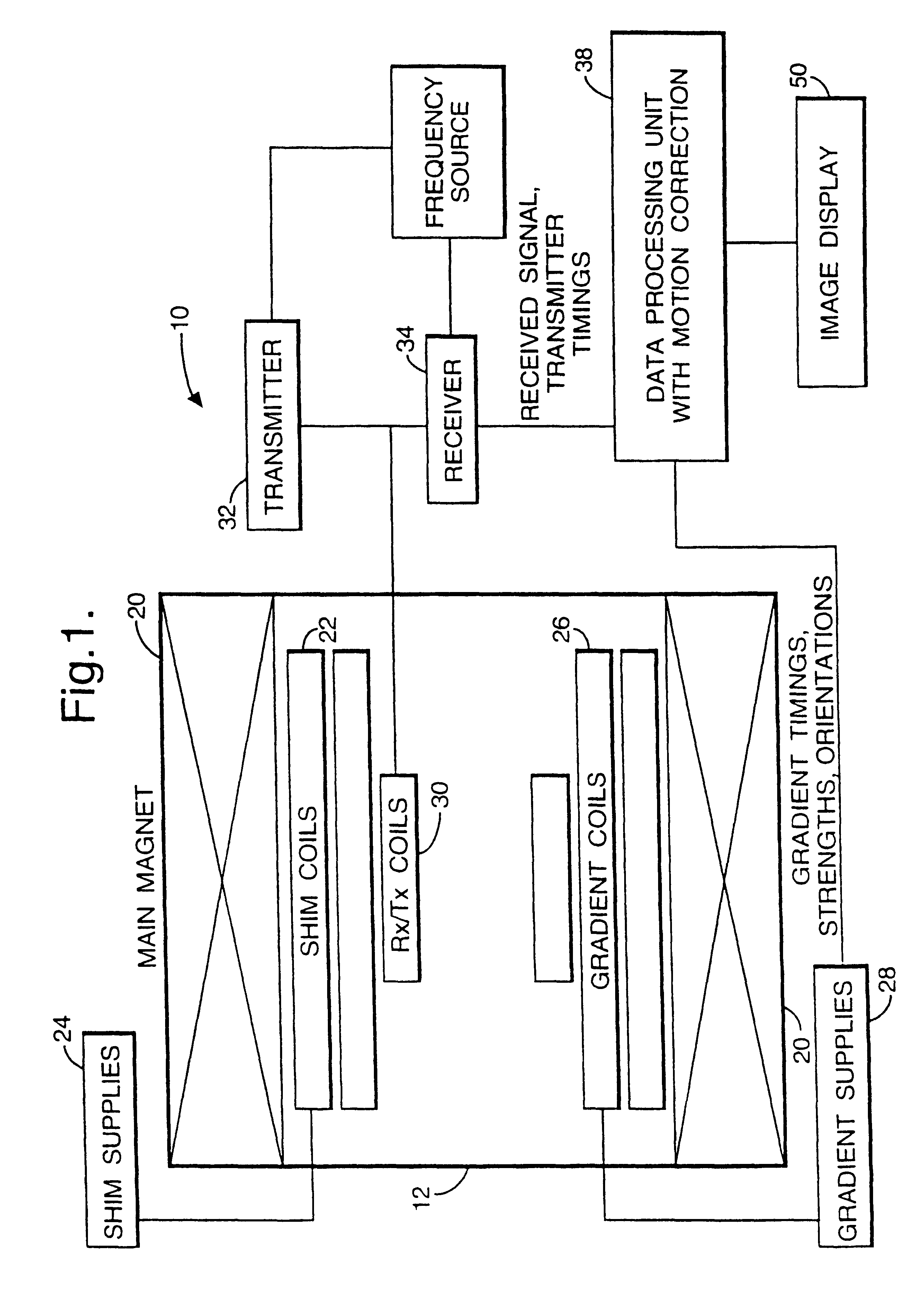
Referring to FIG. 1 there is shown a schematic diagram of a magnetic resonance imaging system 10. The system 10 incorporates a magnetic resonance imaging scanner 12 of conventional type. The scanner 12 has a superconducting main magnet 20 which generates a magnetic field sufficiently strong to cause a net alignment along the field direction of atomic nuclei within a patient. The scanner 12 also includes shim coils 22 in order to correct for undesired inhomogeneities in the magnetic field of the main magnet 20. The magnetic field produced by the shim coils 22 is controlled by a shim coil power supply unit 24.

The resonance frequency of particular atomic nuclei is characteristic of the nucleus and the strength of the applied magnetic field. In order to provide spatial information, a magnetic field gradient is generated by gradient coils such as coils 26. Gradient coils are often arranged to generate gradient fields in three orthogonal directions. The magnetic fields generated by the gr...


PUM


Abstract

The invention relates to a method and apparatus for reducing imaging artifacts in physiological images, such as magnetic resonance imaging images. A model of a physical cause for the image artifact is modelled and the effects of perturbing this model on a focus criterion of the image analyzed so as to optimize the focus criterion. For an optimized focus criterion, the model should reflect the actual physical cause of the image artifact. A focus criterion is a measure of entropy of the image, with an optimized image having reduced entropy.

Description

1. Field of the InventionThe present invention relates to image processing and in particular to image processing techniques whereby image artefacts produced during image acquisition are corrected for in the generation of an output image.2. Discussion of Prior ArtMagnetic Resonance Imaging (MRI) is a widely used technique for medical diagnostic imaging. In a conventional MRI scanner, a patient is placed in an intense static magnetic field which results in the alignment of the magnetic moments of nuclei with non-zero spin quantum numbers either parallel or anti-parallel to the field direction. Boltzmann distribution of moments between the two orientations results in a net magnetisation along the field direction. This magnetisation may be manipulated by applying a radiofrequency (RF) magnetic field at a frequency determined by the nuclear species under study and the strength of the applied field. In almost all cases, the species studied is the nucleus of the hydrogen atom, present in t...

Claims


Application Information

Patent Timeline
Patent Type & Authority Patents(United States)
IPC IPC(8): G06T11/00G01R33/54A61B5/055
CPCG06T11/008G06T2211/424G06T2211/412
Inventor STOYLE, PETER N RHILL, DEREK L GATKINSON, DAVID
Owner NANOGEN RECOGNOMICS BMBH
Why Eureka
Try Eureka