Ocular socket prosthesis

a technology for ocular sockets and prostheses, applied in the field of ocular socket prostheses, can solve the problems of unsightly appearance, major technical difficulties to be overcome, and difficult shells of cosmetic shells, and achieve the effect of reducing the risk of infection

Inactive Publication Date: 2002-02-12
LIONS EYE INST OF WESTERN AUSTRALIA
View PDF8 Cites 29 Cited by
  • Summary
  • Abstract
  • Description
  • Claims
  • Application Information

AI Technical Summary

Benefits of technology

In order to reduce the risk of infection, the prosthesis ma

Problems solved by technology

If this is not done in children the orbit orbital bones fail to develop normally, making wearing of a cosmetic shell difficult, and resulting in an unsightly appearance (Soll, 1982; Kennedy, 1973; Berry, 1991).
However, although,in principle an effective prosthesis is possible, major technical difficulties remain to be overcome.
It is clear from the literature that the ideal orbital implant has not yet been achieved.
However, it is impossible to attach muscles directly to these materials.
However, hydroxyapatite is a hard material and cannot be sutured directly to the tissues; therefore it must still be covered with sclera or Dacron.
Furthermore, hydroxyapatite implants are extremely expensive (Dutton, 1991; McNab, 1995) and are thus not routinely available to patients even in many economically developed countries.
Some studies of keratoprosthesis development have found Proplast to be prone to an inflammatory response and resultant extrusion from the eye (Legeais et al, 1992).
De-epithelialized dermal fat grafts have also been used as primary as well as secondary orbital implants (Smith and Petrelli, 1978; Migliori and Putterman, 1991; Smith e

Method used


Image

  • Ocular socket prosthesis
  • Ocular socket prosthesis
  • Ocular socket prosthesis

Examples


first embodiment

FIG. 4 illustrates a sagittal section showing a prosthesis according to the invention in situ after implantation.

FIG. 5 illustrates a sagittal section of a third preferred embodiment of the invention, in which the prosthesis comprises a homogeneous gel hemisphere and a sponge hemisphere, and in which the sponge hemisphere is strengthened by the presence of a column of gel passing through its centre.

FIG. 6 is a photograph showing an implant according to the first preferred embodiment of the invention.

FIG. 7 shows the appearance of an implant according to the first embodiment at six months after implantation into a rabbit, showing the thick, continuous conjunctival layer.

FIG. 8 is a histological section of the anterior (sponge) half of an implant according to the first embodiment of the invention, showing extensive infiltration of tissue into the implant.

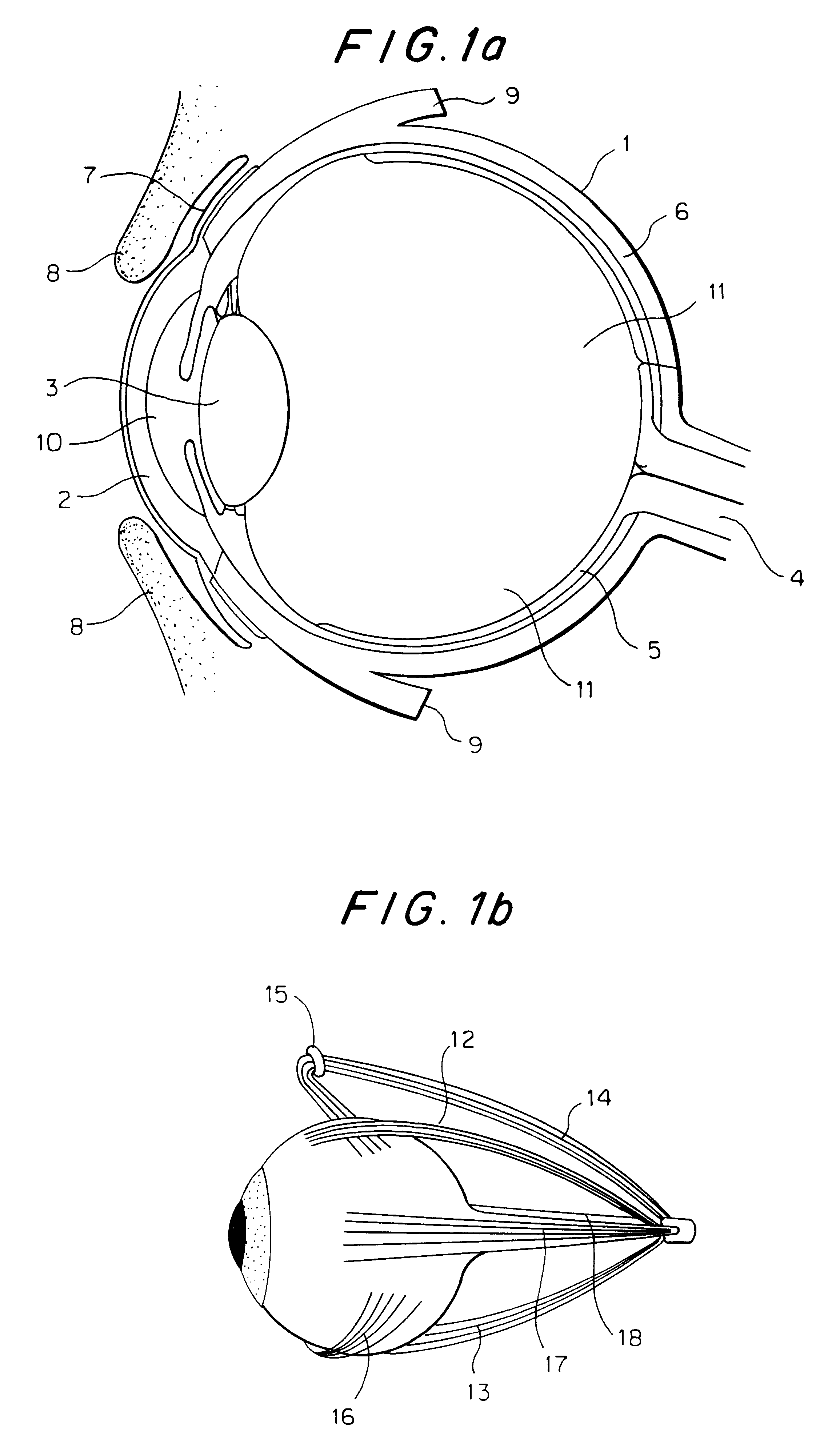
The eyeball and surrounding structures are generally illustrated in FIG. 1a, which represents a sagittal section through the eyeball...

example 1

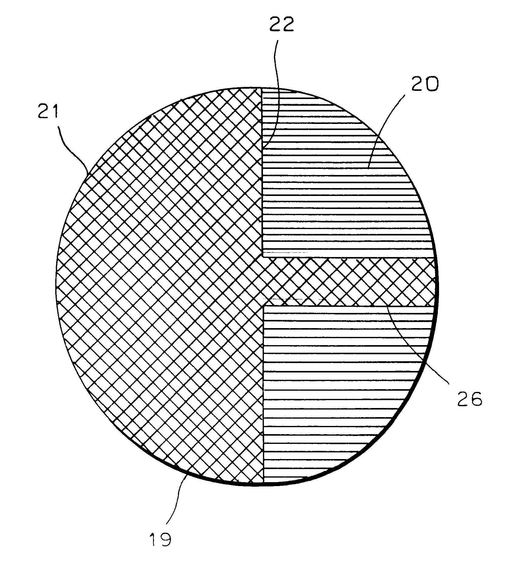
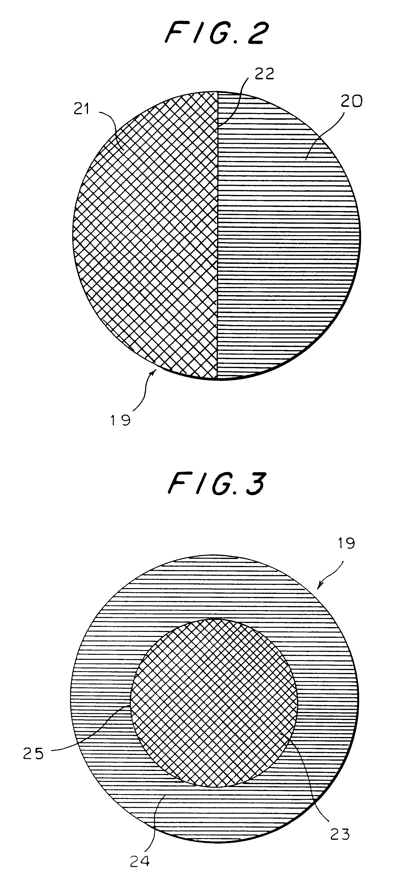
A first preferred embodiment of the invention is illustrated in FIG. 2. This shows a socket prosthesis (19), which is generally spherical in shape, and which comprises an anterior hemisphere (20) which consists of PHEMA in its sponge form, and a posterior hemisphere (21) which consists of the PHEMA polymer in its homogeneous gel form. The interface (22) between the two hemispheres constitutes an interpenetrating polymer network, which provides a permanent chemical attachment between the two hemispheres. In this embodiment the ocular extrinsic muscles are sutured directly into the sponge, so that a covering layer of sclera or Dacron is not required. The fascial sheath of the eyeball (Tenon's capsule) and the conjunctiva are closed over the outside of the prosthesis. The spongy consistency of the anterior hemisphere permits cell ingrowth from the extrinsic muscles and from connective tissues. In contrast, the smooth surface of the solid polymer gel which forms the posterior hemisphere...

example 2

A second preferred embodiment of the invention is illustrated in FIG. 3. The prosthesis (19) is again generally spherical, but in this case consists of a homogeneous gel core (23) surrounded by a sponge layer (24). Again the interface (25) between the core (23) and the outer layer (24) is an interpenetrating polymer network, providing a permanent chemical attachment between the two. It can be seen that in this embodiment the whole surface of the prosthesis is provided by the spongy polymer, and therefore tissue integration can take place over the entire surface. This will minimise the risk of extrusion of the prosthesis, but may not allow as much movement as in the first embodiment.

FIG. 4 is a sagittal section showing a prosthesis according to the first embodiment of the invention in situ after implantation. The prosthesis (19) lies under the sutured conjunctiva (7). The extraocular muscles, of which only the superior rectus (12) and the inferior rectus (13) are shown, and the Tenon...


PUM

PropertyMeasurementUnit
Hydrophilicityaaaaaaaaaa
Biocompatibilityaaaaaaaaaa
Homogeneityaaaaaaaaaa

Abstract

The invention provides an ocular socket prosthesis comprising a hydrogel consisting essentially of a biocompatible hydrophilic polymer onto which tissues can be directly sutured. Preferably the prosthesis comprises the polymer both in its homogeneous gel form and in its sponge form, and the two forms are chemically joined at their interface via an interpenetrating polymer network (IPN). However, it is also contemplated that the prosthesis of the invention may be made predominantly or entirely from the sponge form of the polymer. Methods of production of the prosthesis of the invention and of surgical implantation are also disclosed and claimed.

Description

This invention relates to ocular prostheses, and in particular to prosthetic replacements for the eyeball. In one embodiment, the invention provides an eyeball prosthesis of an improved material.BACKGROUND OF THE INVENTIONIt is common for an eye to have to be removed because of severe trauma, infection, congenital abnormality, untreatable painful glaucoma, or the presence of a tumour. After removal of an eye it is desirable to place a prosthetic globe of similar volume within the eye socket cavity. If this is not done in children the orbit orbital bones fail to develop normally, making wearing of a cosmetic shell difficult, and resulting in an unsightly appearance (Soll, 1982; Kennedy, 1973; Berry, 1991). In an adult, although volume replacement is not necessary in terms of bone development, which is already complete, it is vital for orbital volume to be maintained if the patient is to be fitted with an external cosmetic shell and to obtain a natural appearance and "eye" movement. A...

Claims


Application Information

Patent Timeline
IPC IPC(8): A61F2/14A61L27/52A61L27/16A61L27/00A61L27/56B29D11/02B29D11/00
CPCA61F2/141A61L27/16A61L27/52A61L27/56B29D11/023A61L27/54A61L27/24A61F2/14C08L33/14A61L2430/16
Inventor HICKS, CELIACLAYTON, ANTHONYCHIRILA, TRAIANCRAWFORD, GEOFFREYCONSTABLE, IANFITTON, JANET
Owner LIONS EYE INST OF WESTERN AUSTRALIA
Why Eureka
Try Eureka