Concealed weapons detection system

a concealed weapon and detection system technology, applied in the field of concealed weapon detection systems, can solve the problems of no known concealed weapon detection system, type of system cannot discriminate between concealed weapons and other metallic objects such as belt buckles, coins, watches, etc., and utilizes millimeter-wave efforts, etc., to achieve the effect of successfully detecting non-metallic objects

Inactive Publication Date: 2002-03-19
MACALEESE +1
View PDF50 Cites 297 Cited by
  • Summary
  • Abstract
  • Description
  • Claims
  • Application Information

AI Technical Summary

Benefits of technology

The present invention is directed to a weapons detection system. The preferred weapons detector comprises: a transmitter for producing an output of frequencies of a set of self-resonant frequencies of weaponry; an antenna directing the transmitter output toward locations potentially having weaponry and collecting backscattered signals; a receiver receiving the backscattered signals and operating over a range of the self-resonant frequencies; and a signal processor for detecting presence of a plurality of the self-resonant frequencies in the backscattered signals.

Problems solved by technology

There are no known weapons detection systems on the market today that can detect a concealed weapon from a distance of more than three feet.
This type of system cannot discriminate between concealed weapons and other metallic objects such as belt buckles, jewelry, coins, watches, or calculators.
Likewise, Demma et al. utilizes millimeter-wave efforts but has not been able to detect non-metallic objects successfully.
They also have limited ranging, being effective only to 2 meters.
Infrared technologies, covered extensive in Demma et al., have great difficulty penetrating layers of clothing.
In addition, in warmer climates, a gun carried on the body will take on the same temperatures as the body, making infrared virtually useless.
Miller and Keller employ magnetic field sensors and so will not detect guns made of non-magnetic materials such as aluminum, brass, and copper.
In 1993, the Federal Bureau of Investigation reported there were 11,876 bank robberies in the United States, resulting in a loss of $39.3 million.
There were almost 35,000 armed robberies to convenience stores in the United States, accounting for a $15.7 million loss.
Other countries are facing similar problems.

Method used


Image

  • Concealed weapons detection system
  • Concealed weapons detection system
  • Concealed weapons detection system

Examples


Embodiment Construction

)

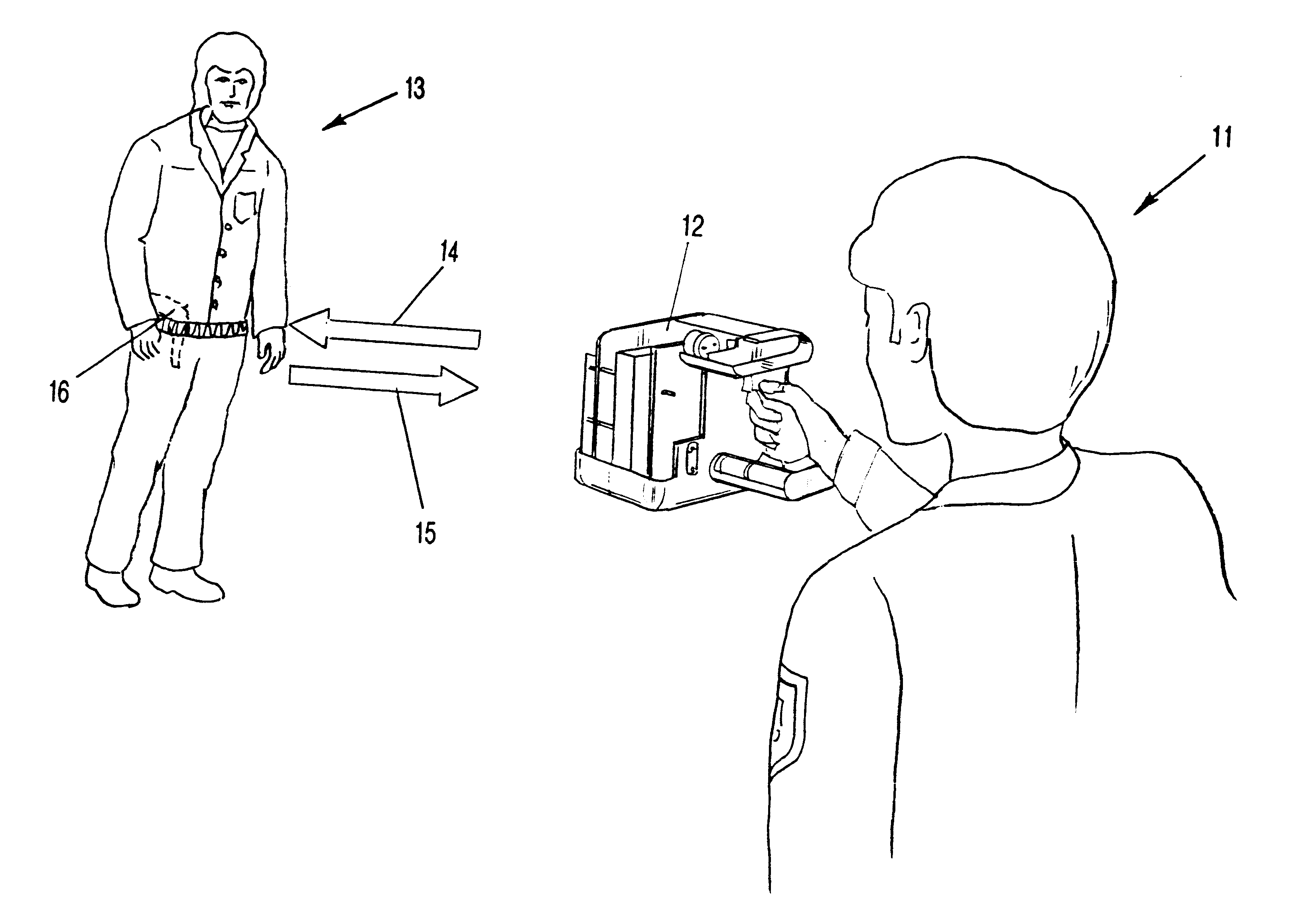
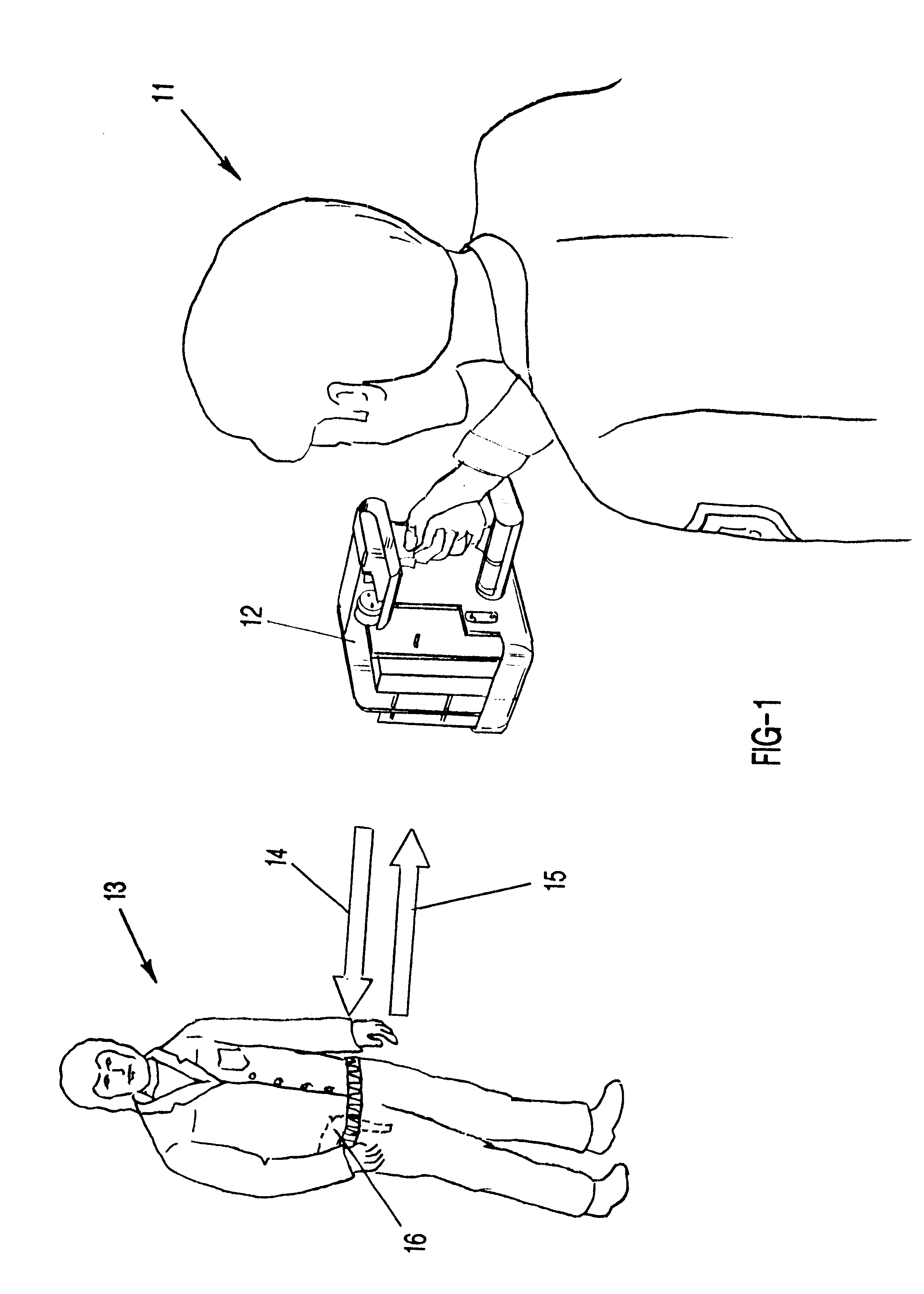
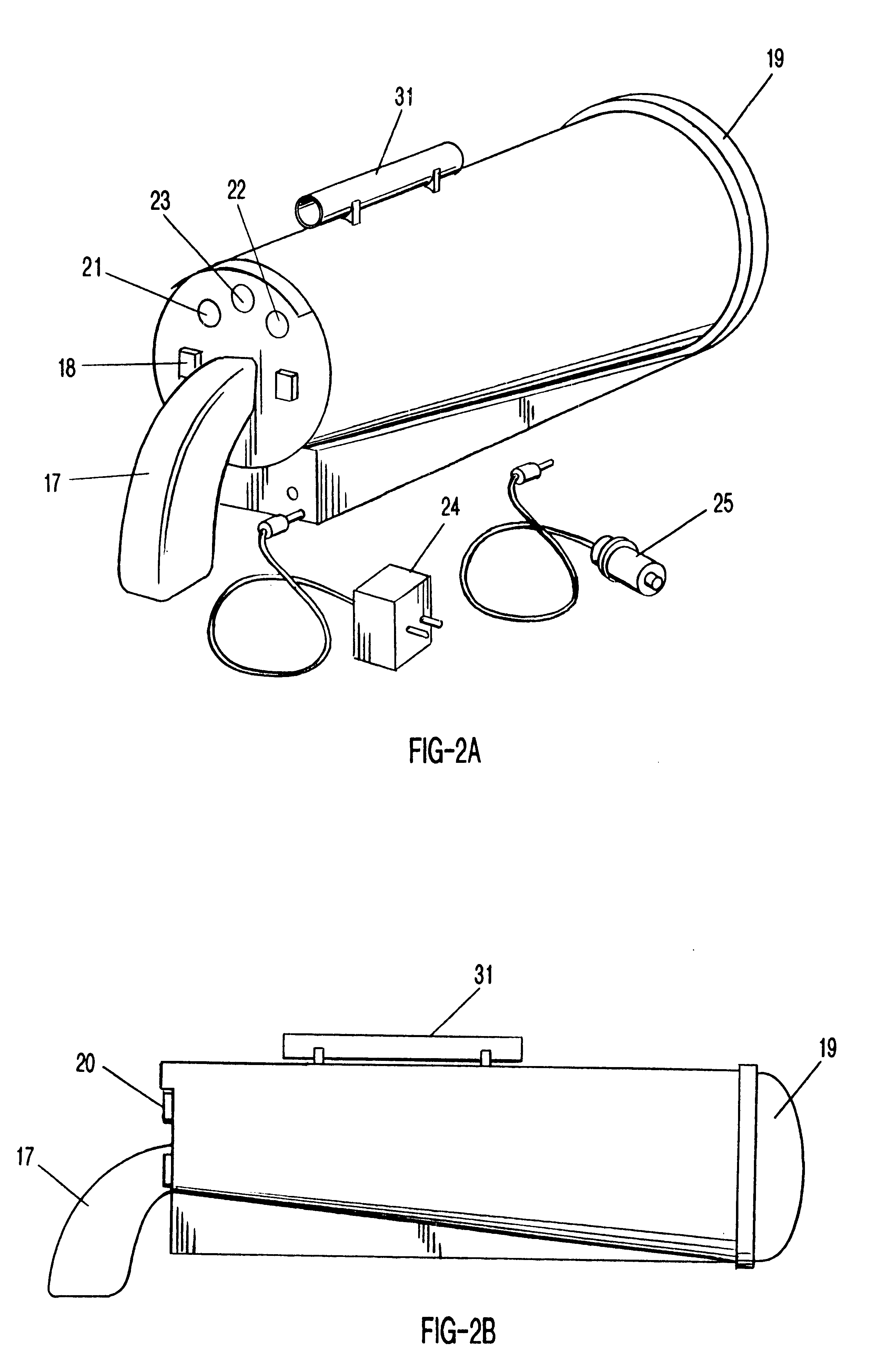
The weapons detection system of the present invention uses a short-pulse radar approach that is stepped over a series of frequencies. The system preferably comprises a trigger, pulser, broad band antenna, amplifier and signal processor. The radar first enters the range finder-mode to determine the distance to the target being surveyed. The range information is used to set the gain of the amplifier so that the output is normalized to range. This normalization permits the waveform returned from the target to be analyzed independent of range. The use of the range gate eliminates background clutter or scatter from overriding the return from the target. The system uses a low voltage pulser to produce a series of microwave pulses transmitted on a compact, broad band antenna. The reflected waveform is returned from the target through the same antenna. The received signal is range-gated and converted to an IF signal. The signal is amplified in the IF amplifier and is then envelop-detected....


PUM


Abstract

A weapons detector (12) and method utilizing radar. The system comprises a transmitter (27) for producing an output (14) of frequencies of a set of self-resonant frequencies of weaponry; an antenna (28) directing the transmitter output toward locations potentially having weaponry and collecting backscattered signals (15); a receiver (29) receiving the backscattered signals (15) and operating over a range of the self-resonant frequencies; and a signal processor (30) for detecting the presence of a plurality of the self-resonant frequencies in the backscattered signals (15). Accuracies of greater than 98% can be obtained at distances, preferably between 4-15 yards. The weapons detector (12) is capable of detecting metal and non-metal weapons (16) on a human body (13) in purses, briefcases and under clothing; and discerning weapons (16) from objects such as belt buckles, coins, keys, calculators, cellular phones.

Description

1. Field of the Invention (Technical Field)The present invention relates to apparatuses and methods for remotely detecting concealed weapons.2. Background ArtThere are no known weapons detection systems on the market today that can detect a concealed weapon from a distance of more than three feet. Virtually every device in operation is an electromagnetic device that requires the use of a portal. An eddy current flows through the portal and when metallic objects create a change in the magnetic flux, it activates a warning signal. This type of system cannot discriminate between concealed weapons and other metallic objects such as belt buckles, jewelry, coins, watches, or calculators.Millitech Corporation of South Deerfield, Mass., may be developing a passive millimeter system. The system apparently would require the use of a portal, a floor plate, a video camera and a cathode ray tube to view the area being searched. Millitech has claimed it was developing a 300 mm aperture camera for...

Claims


Application Information

Patent Timeline
Patent Type & Authority Patents(United States)
IPC IPC(8): G01S13/00G01S13/04G01S7/02G01S7/41G01V3/12G01S7/292G01S13/88
CPCG01S7/417G01S13/04G01S13/887G01V3/12G01S7/4021G01S7/4008G01S7/4017G01S7/52004G01S7/497G01S7/292
Inventor MACALEESE, GREGORY B.HAUSNER, JERRYMENICUCCI, PAUL J.GORMAN, ROBERT H.
Owner MACALEESE
Why Eureka
Try Eureka