
Reticle transfer system

a transfer system and reticle technology, applied in the field of transfer devices, can solve the problems of affecting the pattern etched in the reticle, generating particles, and affecting the processing of semiconductor devices with these sizes,

Inactive Publication Date: 2002-04-02
BROOKS AUTOMATION HLDG LLC +2
View PDF6 Cites 36 Cited by
  • Summary
  • Abstract
  • Description
  • Claims
  • Application Information

AI Technical Summary

Benefits of technology

It is another advantage of the present invention to provide a reticle transfer system which may be precisely and easily positioned to grip a reticle to be transferred.
It is a still further advantage of the present invention that there is no contact with the container door inside of the seal zone (i.e., where the shell meets the door) to prevent particulate generation in that area.
In order to precisely, easily and repeatedly position the gripping mechanism in the desired location to grip and transfer the reticle, the gripping mechanism includes four downwardly extending posts spaced apart from each other so as to contact an outer rim of the container door as the gripping mechanism is lowered into position to grip and transfer the reticle. Once the four posts are seated in contact with the outer rim of the container door, the gripping mechanism is fixed in the proper position so that a pair of grippers within the gripping mechanism may rotate inward and grip the reticle. The posts also allow proper positioning of the gripping mechanism with respect to the container door and support platform within the minienvironment when returning the reticle to the container door or depositing the reticle on the minienvironment support platform.

Problems solved by technology

Particles with these sizes can be very damaging in semiconductor processing because of the small geometries employed in fabricating semiconductor devices.
Unwanted contamination particles which have geometries measuring greater than 0.1 .mu.m substantially interfere with 1 .mu.m geometry semiconductor devices.
Any such contact may generate particles and / or affect the pattern etched in the reticle.
This arrangement takes up a significant amount of space in front of the process tool.

Method used


Image

  • Reticle transfer system
  • Reticle transfer system
  • Reticle transfer system

Examples


Embodiment Construction

The present invention will now be described with reference to FIGS. 1 through 20 which in general relate to a reticle transfer system for transferring reticles between a storage and transfer container and a process tool. While the present invention is described with respect to a SMIF system, it is understood that the present invention may be used with any of various containers for storing and transferring reticles or similar workpieces. Moreover, as explained below, it is additionally contemplated that the present invention operate to transfer bare reticles which have been loaded without a container directly onto a support plate of a reticle transfer system. The present invention complies with and allows compliance with all applicable SEMI standards.

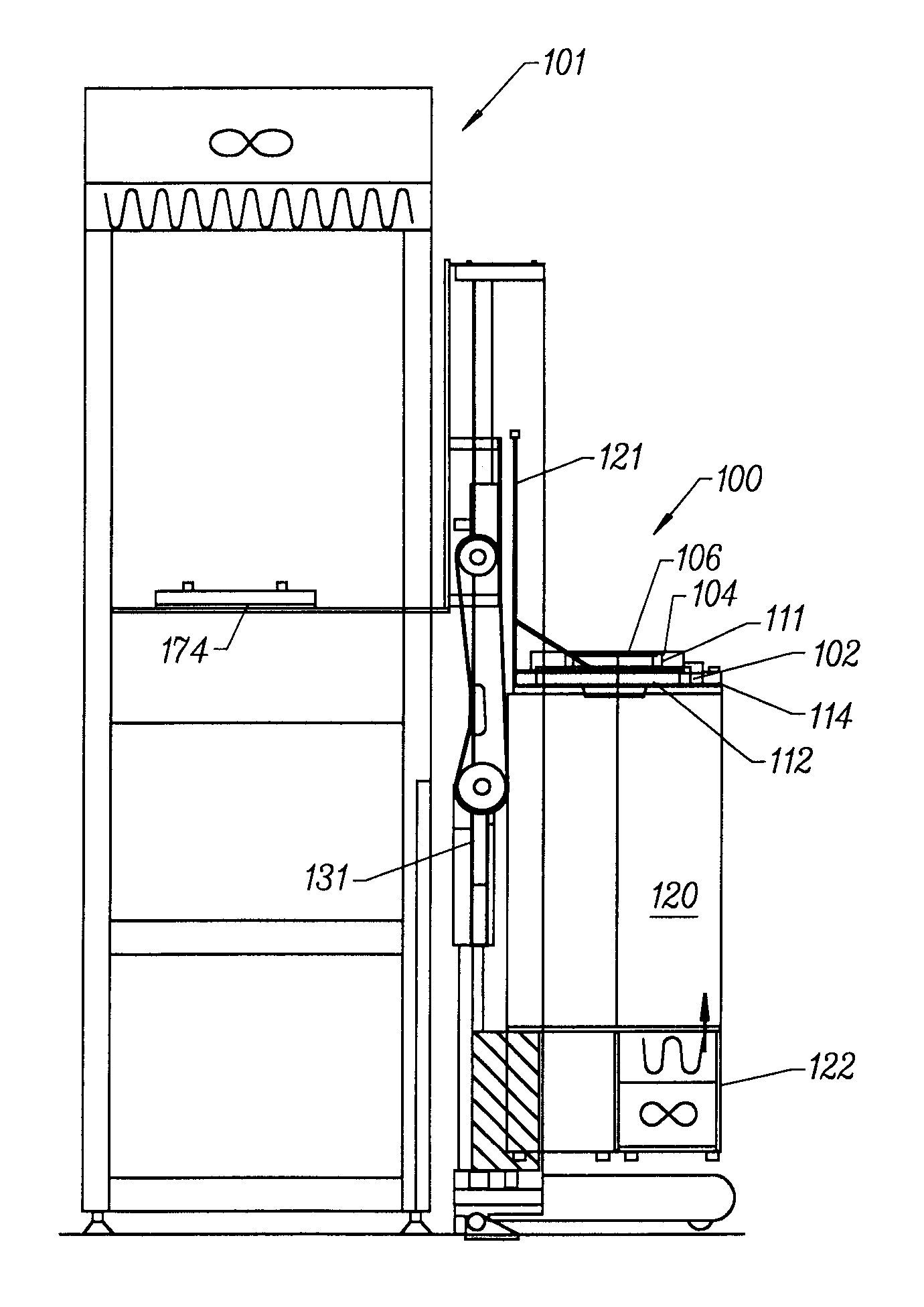
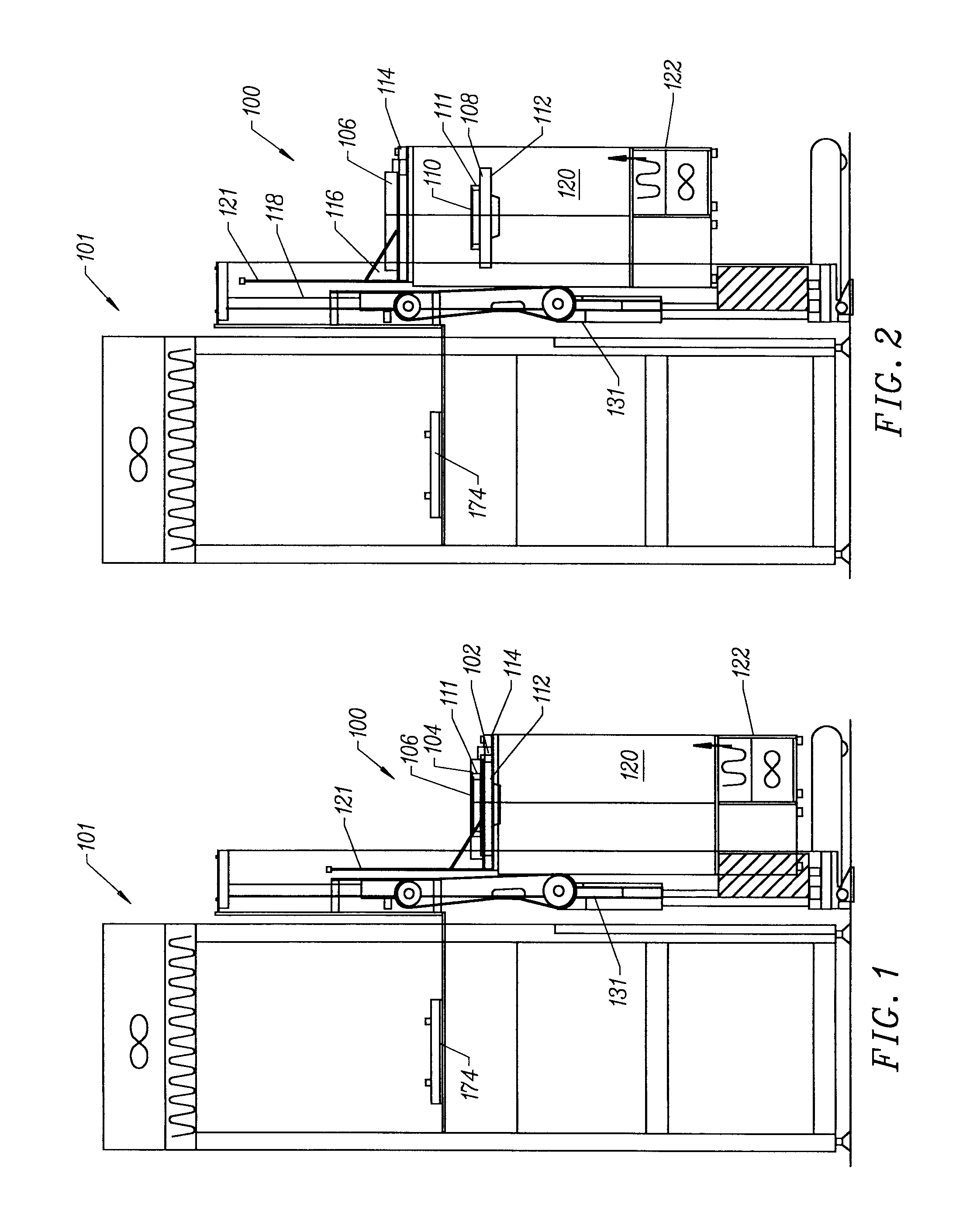
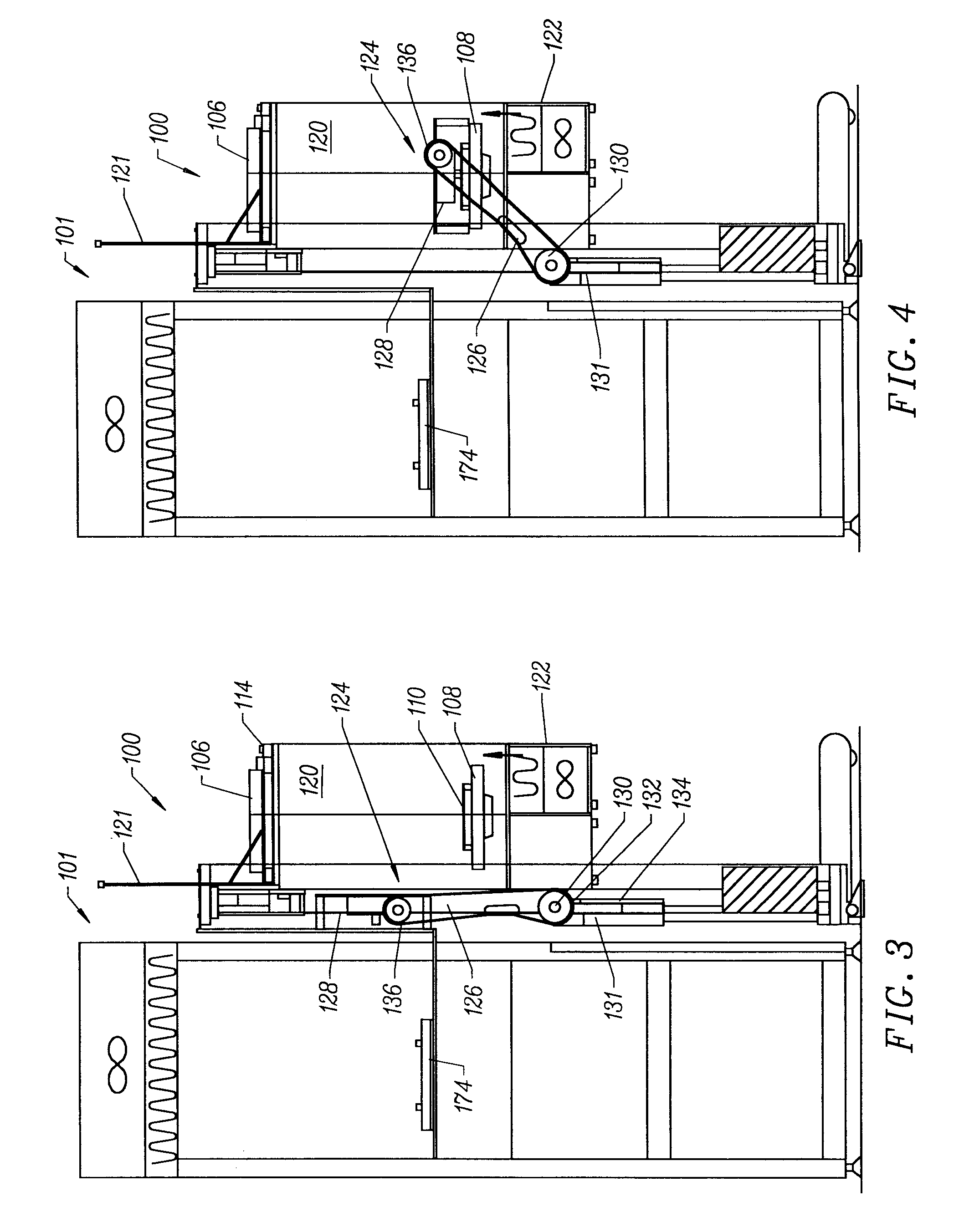
Referring now to FIG. 1, there is shown a reticle transfer system 100 according to the present invention mounted on the front end of a minienvironment 101, which minienvironment is in turn mounted to the front end of a process tool (not ...


PUM


Abstract

A reticle transfer system is disclosed for transferring reticles between a reticle-carrying SMIF container and a process tool. The reticle transfer system according to the present invention includes an arm assembly having a transfer arm and a gripping mechanism affixed to the end of the transfer arm. Once the container carrying the reticle has been opened, the gripping mechanism is rotated and translated to a position adjacent the reticle so that it may access the reticle and transfer it into the minienvironment through an access port in the minienvironment. In order to precisely, easily and repeatedly position the gripping mechanism in the desired location to grip and transfer the reticle, the gripping mechanism includes four downwardly extending posts spaced apart from each other so as to contact an outer rim of the container door as the gripping mechanism is lowered into position to grip and transfer the reticle. Once the four posts are seated in contact with the outer rim of the container door, the gripping mechanism is fixed in the proper position so that a pair of grippers within the gripping mechanism may rotate inward and grip the reticle. The posts also allow proper positioning of the gripping mechanism with respect to the container door and support platform within the minienvironment when returning the reticle to the container door or depositing the reticle on the minienvironment support platform.

Description

1. Field of the InventionThe present invention relates to a transfer device for use with standardized mechanical interface (SMIF) systems for facilitating semiconductor wafer fabrication, and in particular to a transfer mechanism for gripping and transporting a reticle between a storage and transport container and a process tool.2. Description of the Related ArtA SMIF system proposed by the Hewlett-Packard Company is disclosed in U.S. Pat. Nos. 4,532,970 and 4,534,389. The purpose of a SMIF system is to reduce particle fluxes onto semiconductor wafers during storage and transport of the wafers through the semiconductor fabrication process. This purpose is accomplished, in part, by mechanically ensuring that during storage and transport, the gaseous media (such as air or nitrogen) surrounding the wafers is essentially stationary relative to the wafers and by ensuring that particles from the ambient environment do not enter the immediate wafer environment.The SMIF system provides a cl...

Claims


Application Information

Patent Timeline
IPC IPC(8): G03F7/20H01L21/67H01L21/677H01L21/687
CPCG03F7/70741H01L21/67778H01L21/68707Y10S414/141Y10S414/137
Inventor BONORA, ANTHONY C.FOSNIGHT, WILLIAM J.SHENK, JOSHUA W.
Owner BROOKS AUTOMATION HLDG LLC
Learn More