
Device and method for reading information stored in a phosphor layer

a technology of information storage and phosphor layer, which is applied in the direction of instruments, television systems, and television system scanning details, etc., can solve the disadvantages of light emitted by the radiation source and exciting the phosphor layer, introduce noise in the x-ray image, and disadvantages of filter disadvantages,

Inactive Publication Date: 2002-04-09
AGFA GEVAERT HEALTHCARE
View PDF9 Cites 37 Cited by
  • Summary
  • Abstract
  • Description
  • Claims
  • Application Information

AI Technical Summary

Benefits of technology

It may also be possible, as disclosed in U.S. Pat. No. 4,953,038, to arrange--in addition to a reflective layer--a filter in the optical path between the phosphor layer and an imaging means for absorbing the excitation radiation. The imaging means for imaging the radiation emitted by the phosphor layer may be implemented, for example, in the form of an optical fiber arrangement. Such an optical fiber arrangement has the additional advantage over the arrangement disclosed in U.S. Pat. No. 4,953,038 that the filter layer can be made thinner, so that a greater portion of the radiation emitted by the phosphor layer can be collected and imaged on the receiver. Because scattering of the emitted radiation is also reduced, the image is sharper and of higher quality.
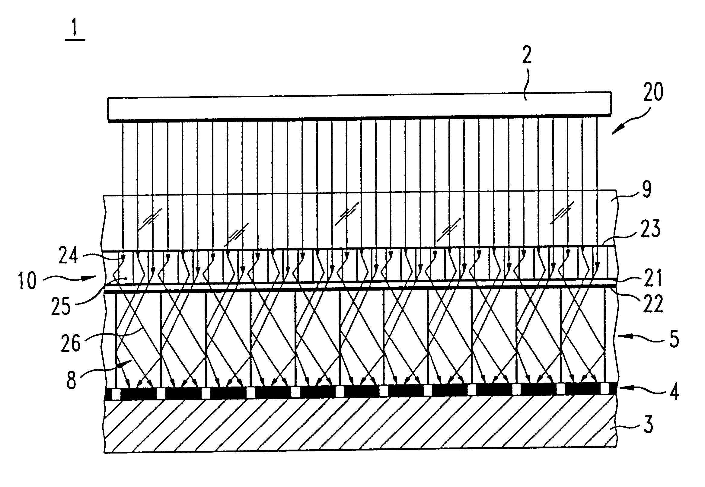
According to an advantageous embodiment of the invention, the phosphor layer includes a special phosphor with a special crystalline needle-shaped structure. A phosphor of this type is known, for example, from the European patent application EP 0 751 200 A1. This special phosphor has a plurality of "needles" which guide both the excitation radiation and the emitted radiation. The phosphor is prepared by growing crystalline "needles" having a base area of approximately between 1 and 25 .mu.m.sup.2 and a height corresponding to the desired layer thickness of the phosphor layer. Excitation radiation impinging normal to the surface of the phosphor layer is guided in each "needle" essentially without being scattered until reaching a color center in the crystal lattice in which the information is stored. The emitted radiation produced through excitation of the color center is guided in the respective "needle." Depending on the reflective index between the "needles," the respective emitted radiation is a reflected and guided out of the "needle." By using this special phosphor, scattering of the excitation radiation inside the phosphor carrier is practically eliminated. It particular, with information stored in the phosphor layer being read out row-by-row, scattering of the excitation radiation perpendicular to the row direction can be detrimental, since color centers can also be excited which are located in a row of the phosphor layer different from the row currently being read. Consequently, image radiation can "get lost," i.e., cannot be detected by the receiver. Scattering of the emission radiation within the phosphor carrier layer is also eliminated, so that the emitted radiation can be detected by the receiver with excellent spatial resolution.
The reflective layer arranged between the phosphor layer and the receiver reflects the excitation radiation which passes through the transparent carrier and the phosphor layer and reintroduces the excitation radiation into the phosphor layer. As a result, the color centers in the phosphor layer are once more excited and emit radiation. Accordingly, the phosphor layer emits an increased amount of radiation which can then be detected by the receiver. This reproduces the information with better quality and enhanced sharpness.
According to another advantageous embodiment of the invention, a reflective layer for reflecting the emission radiation emitted by the phosphor layer is arranged between the radiation source and the phosphor layer. This reflective layer reflects the emission radiation, which is emitted by the phosphor layer towards the side of the phosphor layer facing away from the receiver, towards the receiver. The reflected radiation can thus also be detected by the receiver, further improving the reproduction of the information.

Problems solved by technology

When this method is used for reading the information stored in the phosphor layer, light emitted by the radiation source and exciting the phosphor layer may disadvantageously also be collected by the optical fiber arrangement and conveyed to the CCD.
This tends to introduce noise in the x-ray image which is detected by the CCD.
However, such filter disadvantageously tends to be relatively thick, with the filter thickness typically exceeding 0.3 mm.
As a result, the CCD may not be able to detect the exact location from which the light is collected.
In addition, radiation emitted by the phosphor layer may even be "lost" when passing through the filter and may thus escape detection by the CCD.
The visual representation of the x-ray image may therefore be distorted and of poor quality.
It particular, with information stored in the phosphor layer being read out row-by-row, scattering of the excitation radiation perpendicular to the row direction can be detrimental, since color centers can also be excited which are located in a row of the phosphor layer different from the row currently being read.
Consequently, image radiation can "get lost," i.e., cannot be detected by the receiver.

Method used


Image

  • Device and method for reading information stored in a phosphor layer
  • Device and method for reading information stored in a phosphor layer
  • Device and method for reading information stored in a phosphor layer

Examples


first embodiment

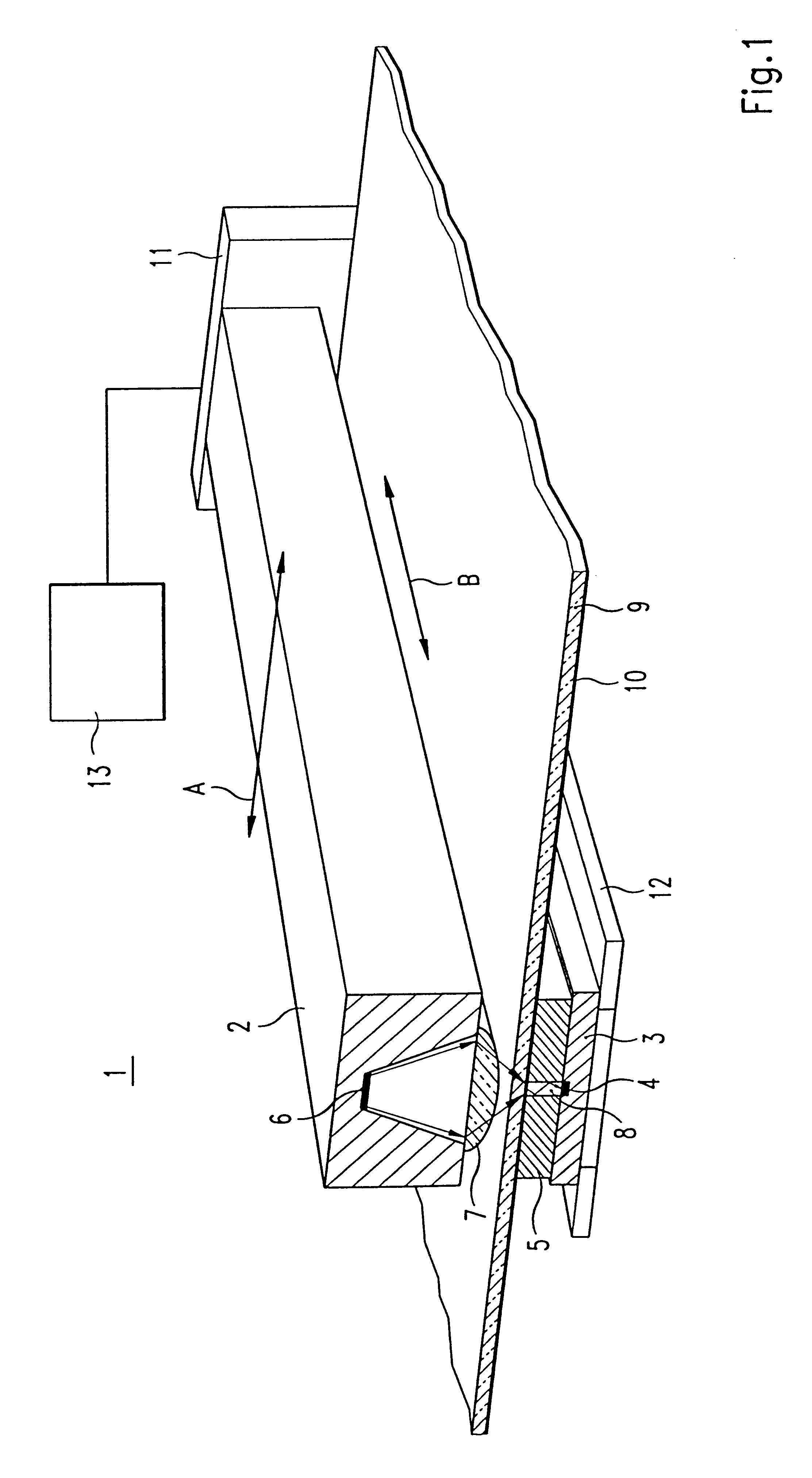
FIG. 1 shows schematically a perspective diagram of the device according to the invention for reading information stored in a phosphor layer. A reading device 1 is used to read image information from a phosphor layer 10. The image information is produced by irradiating the phosphor layer 10 with x-rays. The reading device I includes a radiation source 2 which in this embodiment is implemented as a line light source having a plurality of laser diodes arranged side by side. The line light source 2 of the present example includes 4096 laser diodes arranged in parallel in a row. The laser diodes can be used to excite a single row of the phosphor layer 10. An exemplary laser diode 6 is shown in FIG. 1. The laser diodes of the line light source 2 are oriented perpendicular to the phosphor layer 10, so that the radiation emitted by the individual laser diodes impinges directly on the phosphor layer 10. The line light source 2 essentially extends across the entire width B used to store the ...

second embodiment

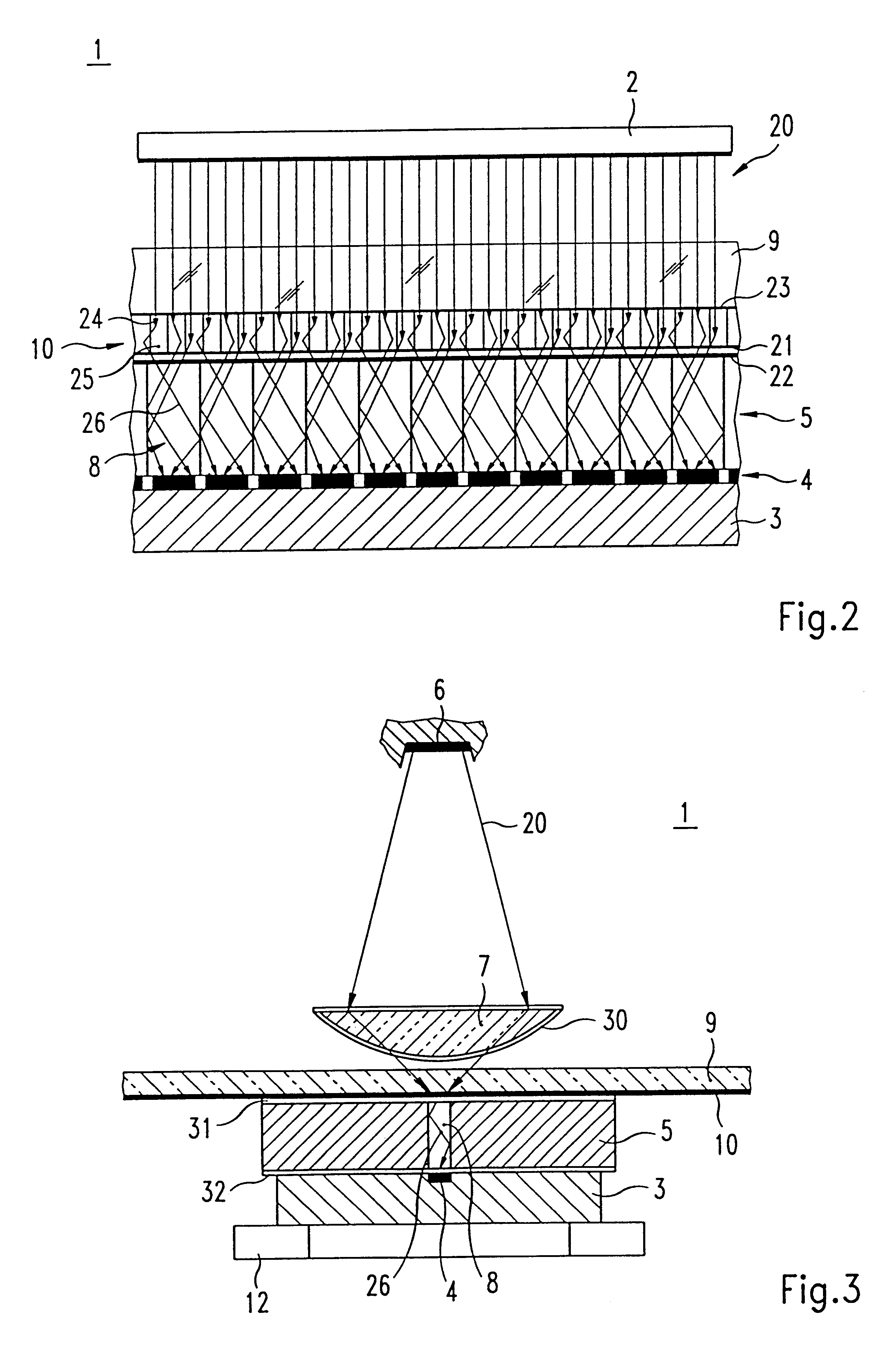
Reflective layers for reflecting the stimulating radiation 20 can also be placed at different locations in the reading device of the invention. Such reflective layers need not be placed between the phosphor layer 10 and the optical fiber arrangement 5 in the manner illustrated with reference to the embodiment of FIG. 2. FIG. 3 shows schematically a diagram of the reading device of the invention. The reading device 1 is shown as viewed along a row. One of the exemplary laser diodes 6 is illustrated, with the laser beam 20 being focused by the focusing lens 20 through the transparent carrier 9 on the phosphor layer 10. As mentioned above, the phosphor layer 10 is simulated by the stimulating radiation to emit an emission radiation which is conveyed through the optical fiber arrangement 5 to the linear CCD 3. One exemplary optical fiber 8 of the optical fiber arrangement 5 is illustrated in FIG. 3. The emission radiation 26 emitted by the phosphor layer is conveyed through the optical ...


PUM


Abstract

A device (1) and a method for reading information stored in a phosphor layer (10) is disclosed. The device (1) includes a transparent carrier material (9) on which the phosphor layer (10) to be read is disposed. A radiation source (2) emits an excitation radiation (20) to excite the phosphor layer (10), which in turn emits an emission radiation (26). The emission radiation (26) can be received by a receiver (3). The radiation source (2) is arranged on one side of the transparent carrier material (9), whereas the receiver (3) is arranged on the other side of the transparent carrier material (9), thereby defining an optical path between the radiation source (2) and the receiver (3). According to the invention, a reflective layer (21, 22; 30, 31, 32) for reflecting at least a portion of the excitation radiation (20) is arranged in the optical path.

Description

1. Field of the InventionThe present invention relates to a device and a method for reading information stored in a phosphor layer wherein an excitation radiation is emitted in the direction of a transparent carrier material having disposed thereon the phosphor layer to be read, the phosphor layer in response emits an emission radiation and the emission radiation emitted by the phosphor layer is received.In particular for medical purposes, an image is generated of an object, for example a patient, using x-rays, wherein the image is stored in a phosphor layer as a latent image. To read the x-ray image stored in the phosphor layer, the phosphor layer is excited by a radiation source. This excitation by the radiation sauce causes the phosphor layer to emit light having an intensity corresponding to the x-ray image stored in the phosphor layer. The light emitted by the phosphor layer is received by a receiver, so that the x-ray image stored in the phosphor layer can be made visible. The...

Claims


Application Information

Patent Timeline
IPC IPC(8): G03B42/00G03B42/02G03B42/08G02B6/04H01L31/00H04N5/30H04N3/00H04N1/191H04N1/028H04N1/23
CPCG01T1/2012G03B42/02G03B42/08H04N5/2254H04N5/32H04N2201/0404H04N1/193H04N1/12H04N23/55H04N23/30
Inventor GEBELE, HERBERTLEBLANS, PAULMULLER, JURGENTHOMA, RALPH
Owner AGFA GEVAERT HEALTHCARE
Learn More