
Modified design representation for fast fault simulation of an integrated circuit

a fault simulation and integrated circuit technology, applied in the field of system and method of fault simulation and modeling, can solve the problems of complex designs, inability to easily model logic blocks in hardware accelerators, and inability to use hardware accelerator primitives to model logic blocks in designs

Inactive Publication Date: 2002-04-09
BELL SEMICON LLC
View PDF23 Cites 15 Cited by
  • Summary
  • Abstract
  • Description
  • Claims
  • Application Information

AI Technical Summary

Benefits of technology

It is therefore an advantage of an embodiment of the present invention that fault simulation speed can be improved when a design includes both hardware and software modeled design elements.

Problems solved by technology

For example, defects in a fabricated transistor can cause a logic gate to sense a single value at an input port, regardless of the input value actually applied to that input port.
Fault simulation is a resource-intensive type of simulation, particularly when performed exclusively in software.
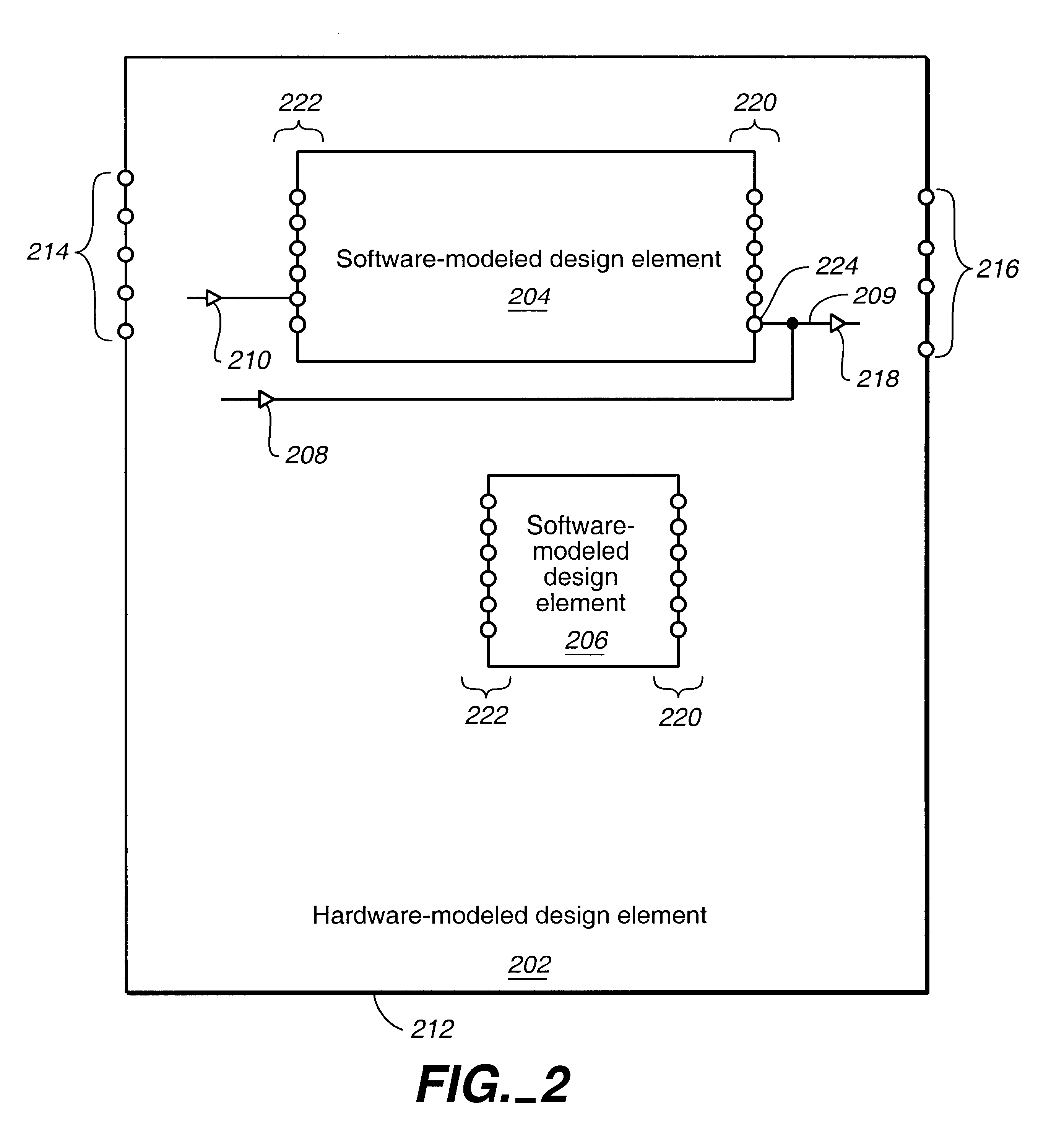
Complex designs, however, often include logic blocks that are not easily modeled in a hardware accelerator.
For example, some logic blocks in a design may not lend themselves to modeling using the primitives available in a hardware accelerator.
Furthermore, some designs are so large and complex that the designer does not have enough primitive logic gates available in the hardware accelerator to model the entire design.
This coordination, however, typically slows down the simulation because of the increased communications and context switches between the two portions of the hybrid fault simulation (hardware and software).
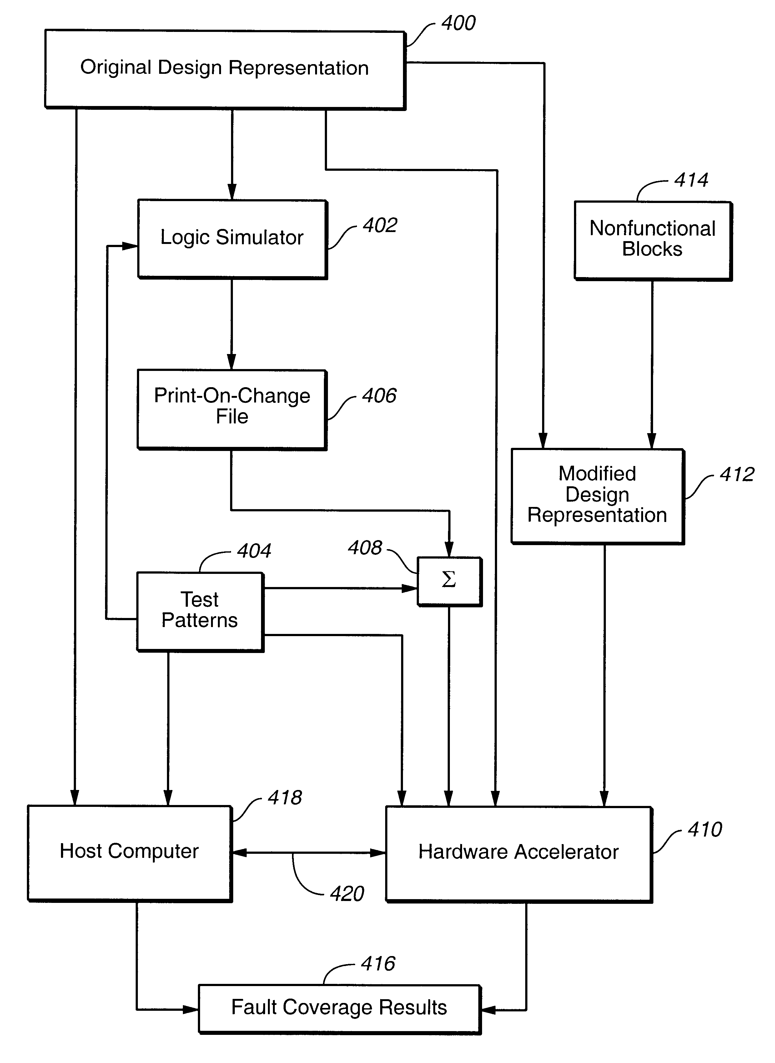
During fault simulation of a large design containing many software-modeled design elements, the communication between the host computer (simulating the software-modeled design element) and the hardware accelerator (simulating the hardware-modeled design element) has been identified as a primary cause of slow simulation speeds.

Method used


Image

  • Modified design representation for fast fault simulation of an integrated circuit
  • Modified design representation for fast fault simulation of an integrated circuit
  • Modified design representation for fast fault simulation of an integrated circuit

Examples


Embodiment Construction

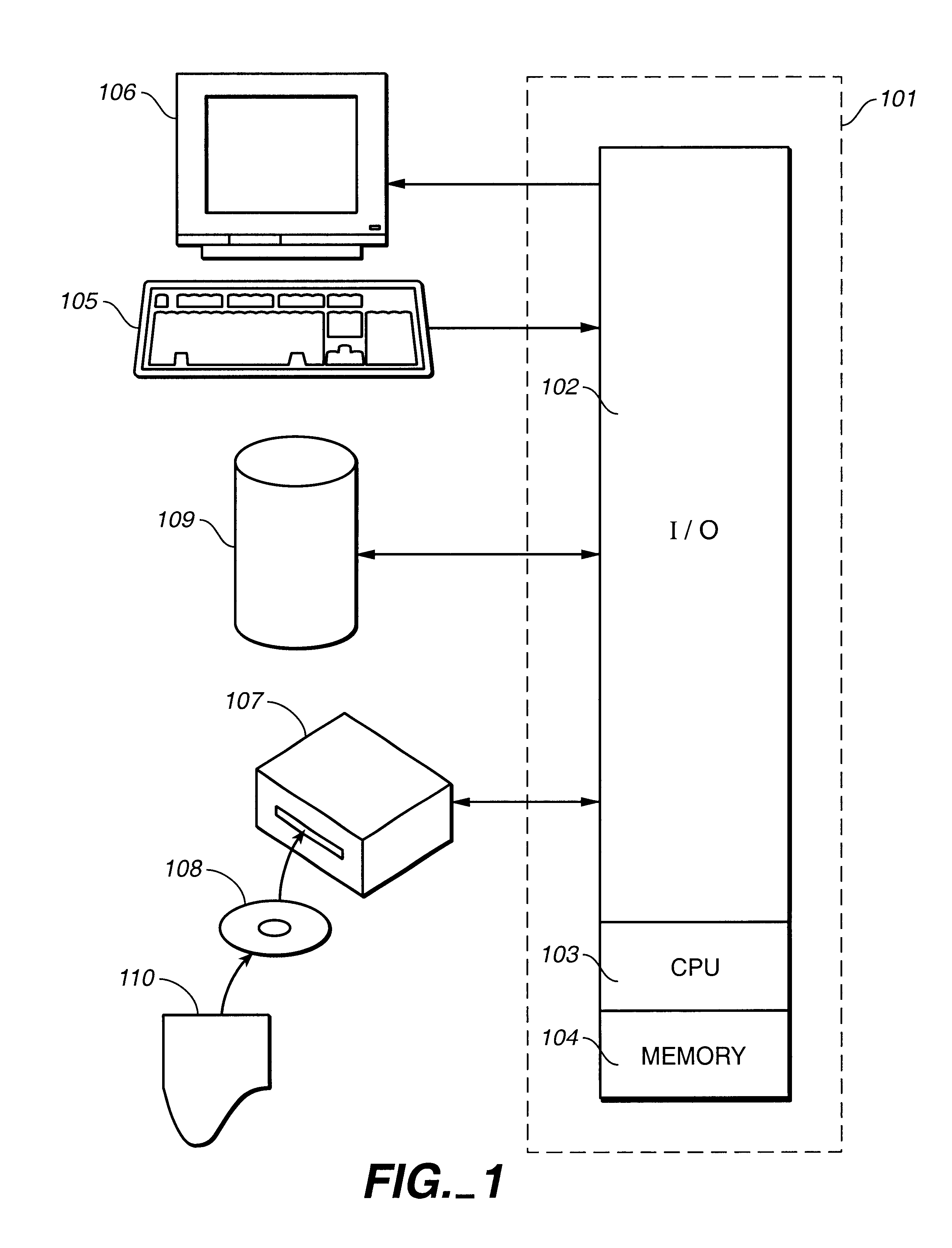
One operating environment in which the present invention is potentially useful encompasses the general purpose computer. In such a system, data and program files may be input to the computer, which reads the files and executes the programs therein. Some of the elements of a general purpose computer are shown in FIG. 1, wherein a processor 101 is shown having an input / output (I / O) section 102, a Central Processing Unit (CPU) 103, and a memory section 104. The present invention is optionally implemented in software devices loaded in memory 104 and / or stored on a configured CD-ROM 108 or storage unit 109 thereby transforming the computer system in FIG. 1 to a special purpose machine for implementing the present invention.

The I / O section 102 is connected to keyboard 105, display unit 106, disk storage unit 109, and disk drive unit 107. Generally, in contemporary systems, the disk drive unit 107 is a CD-ROM driver unit capable of reading the CD-ROM medium 108, which typically contains pr...


PUM


Abstract

A system and method perform a two-pass fault simulation on an original design representation including a software-modeled design element and a hardware-modeled design element. Logic simulation generates input stimulus for a port on the boundary of the software-modeled design element and the hardware-modeled design element, where such ports are output ports of the software-modeled design element and input ports of the hardware-modeled design element. The input stimulus is merged with test patterns for the original design representation. A modified design representation is generated by replacing the software-modeled design element with a nonfunctional block. Most or all possible faults in the hardware-modeled design representation are seeded. The modified design representation is fault simulated in a first pass using the merged input stimulus and test patterns. Any unseeded faults from the first pass and other possible faults in the software-modeled design representation are then seeded and the original design representation is fault simulated in a second pass. The fault coverage results of the two passes are aggregated to generate an overall fault coverage for the original design representation.

Description

1. Field of the InventionThe present invention pertains generally to electrical computers and data processing systems and more particularly to systems and methods for simulation and modeling.2. Description of Related ArtA modern integrated circuit design and manufacturing process typically involves several stages. A Design stage is an initial phase in which a designer preferably captures a prototype circuit design using schematic design tools or preferably a Hardware Description Language (HDL). The prototype design is eventually recorded in a design representation such as a netlist or a design database. A designer may cycle in and out of the Design stage when guiding a design through multiple design iterations.A Verification stage is a "testing" phase in which a prototype design is logically tested to ensure that it matches its functional specification, that is, to verify the correctness of the design. Generally, verification involves logic simulation to verify that the circuit: (a)...

Claims


Application Information

Patent Timeline
IPC IPC(8): G06F17/50G06F9/45G06F11/26
CPCG06F11/261
Inventor AKIN, MICHELLE R.
Owner BELL SEMICON LLC
Learn More