Laser plasma source for extreme ultraviolet lithography using a water droplet target

a plasma source and target technology, applied in photomechanical equipment, instruments, nuclear engineering, etc., can solve the problems of inability to achieve the effect of extreme ultraviolet lithography, difficult to construct tape driven targets, cumbersome replacement of tapes,

Inactive Publication Date: 2002-04-23
UNIV OF CENT FLORIDA RES FOUND INC
View PDF7 Cites 158 Cited by
  • Summary
  • Abstract
  • Description
  • Claims
  • Application Information

AI Technical Summary

Problems solved by technology

None of these approaches have been found useful in the 17 or more years since that time.
However, tape driven targets are limited mass targets that are difficult to construct, prone to breakage and produce low velocity debris that can damage the other components such as the mirrors in the laser output system.
Furthermore, using and replacing the tapes is generally cumbersome and costly.
Solid targets also have many problems.
All of these debris size particles can degrade the surface quality or the operating performance by over coating the optical elements in the laser output system.
Unfortunately, it has been found that with extended life (>10.sup.7 shots), ions from this plasma still sputter or ablate the surface layers of the multi-layer EUV lithography optical systems.

Method used


Image

  • Laser plasma source for extreme ultraviolet lithography using a water droplet target
  • Laser plasma source for extreme ultraviolet lithography using a water droplet target
  • Laser plasma source for extreme ultraviolet lithography using a water droplet target

Examples


Embodiment Construction

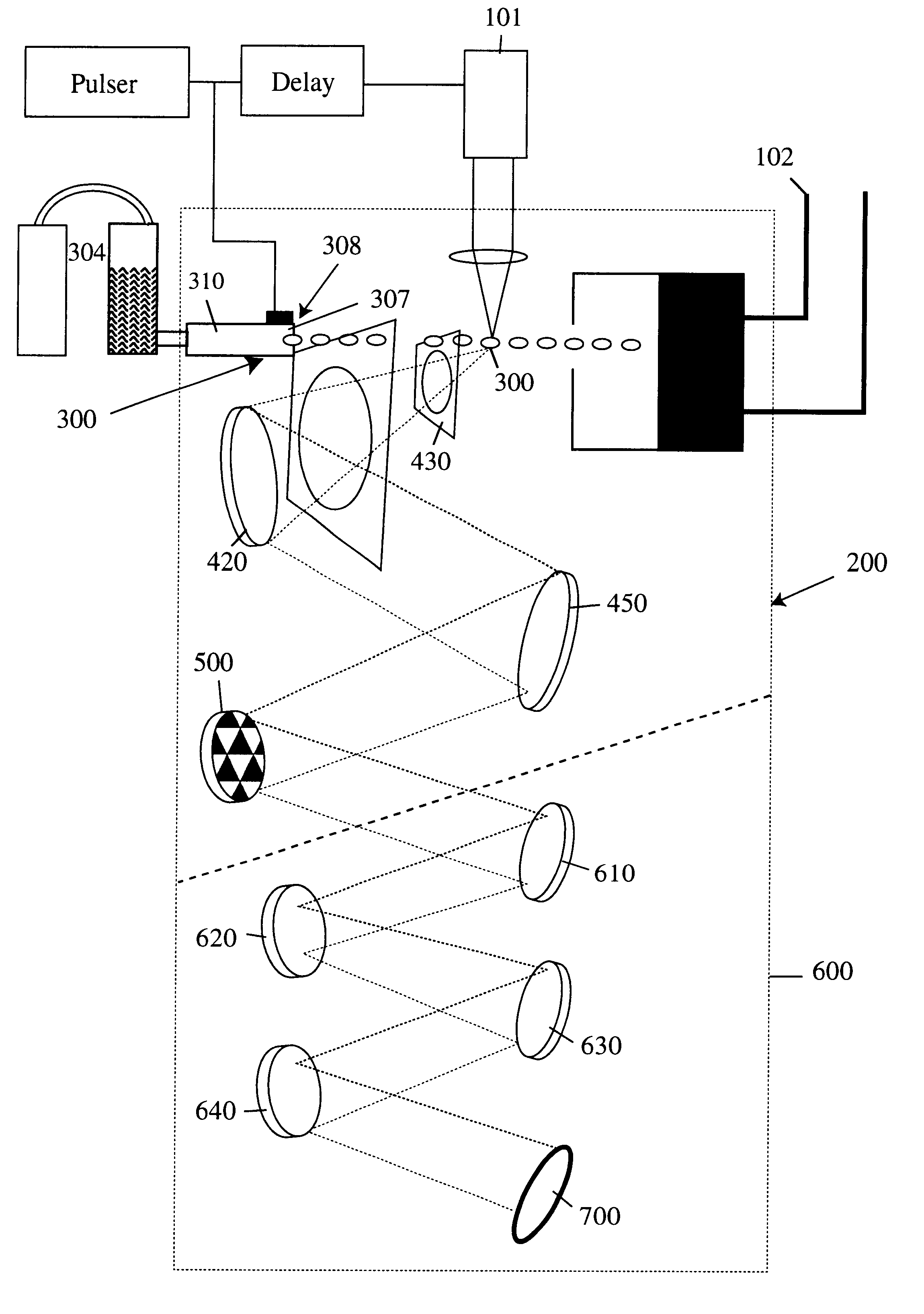
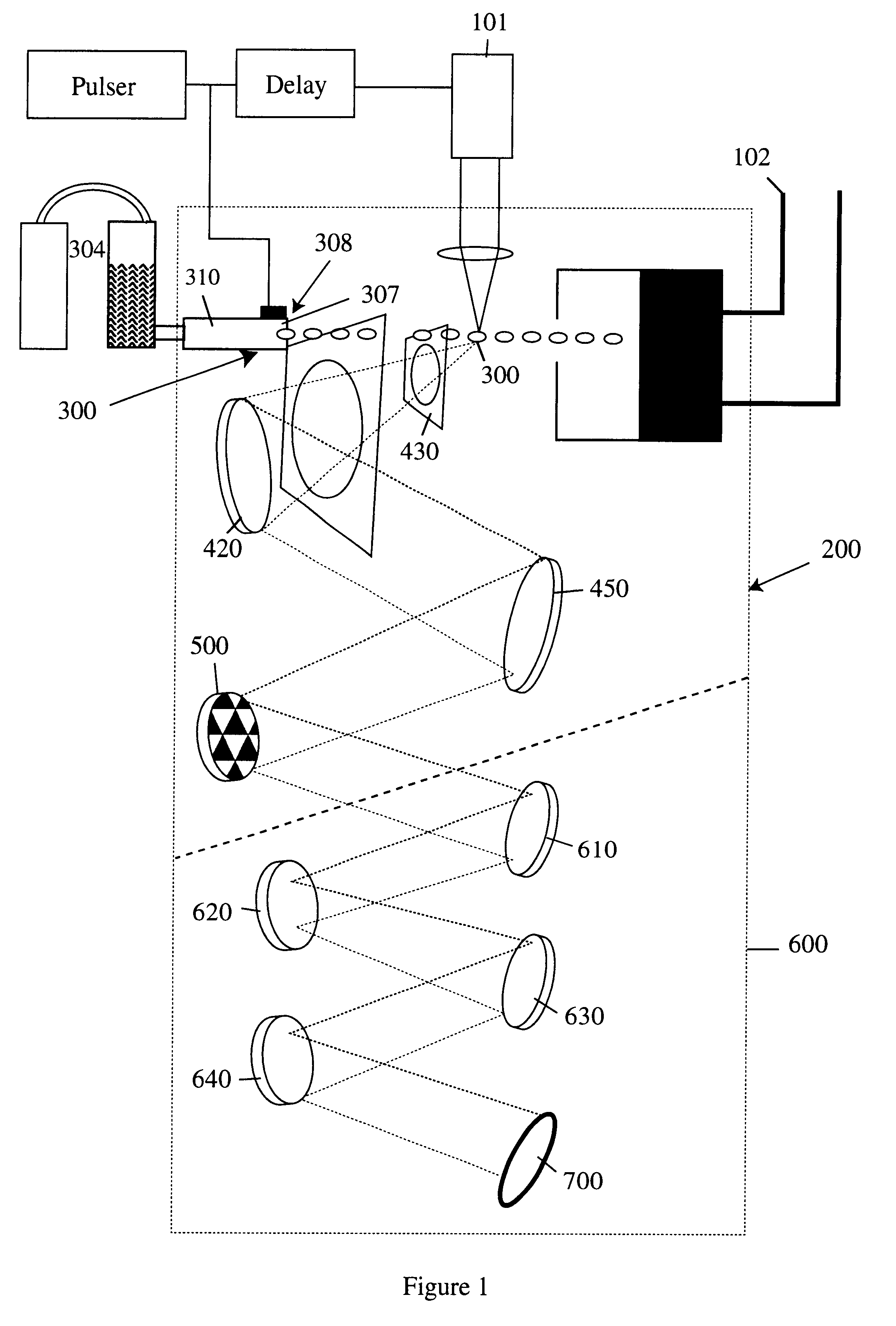
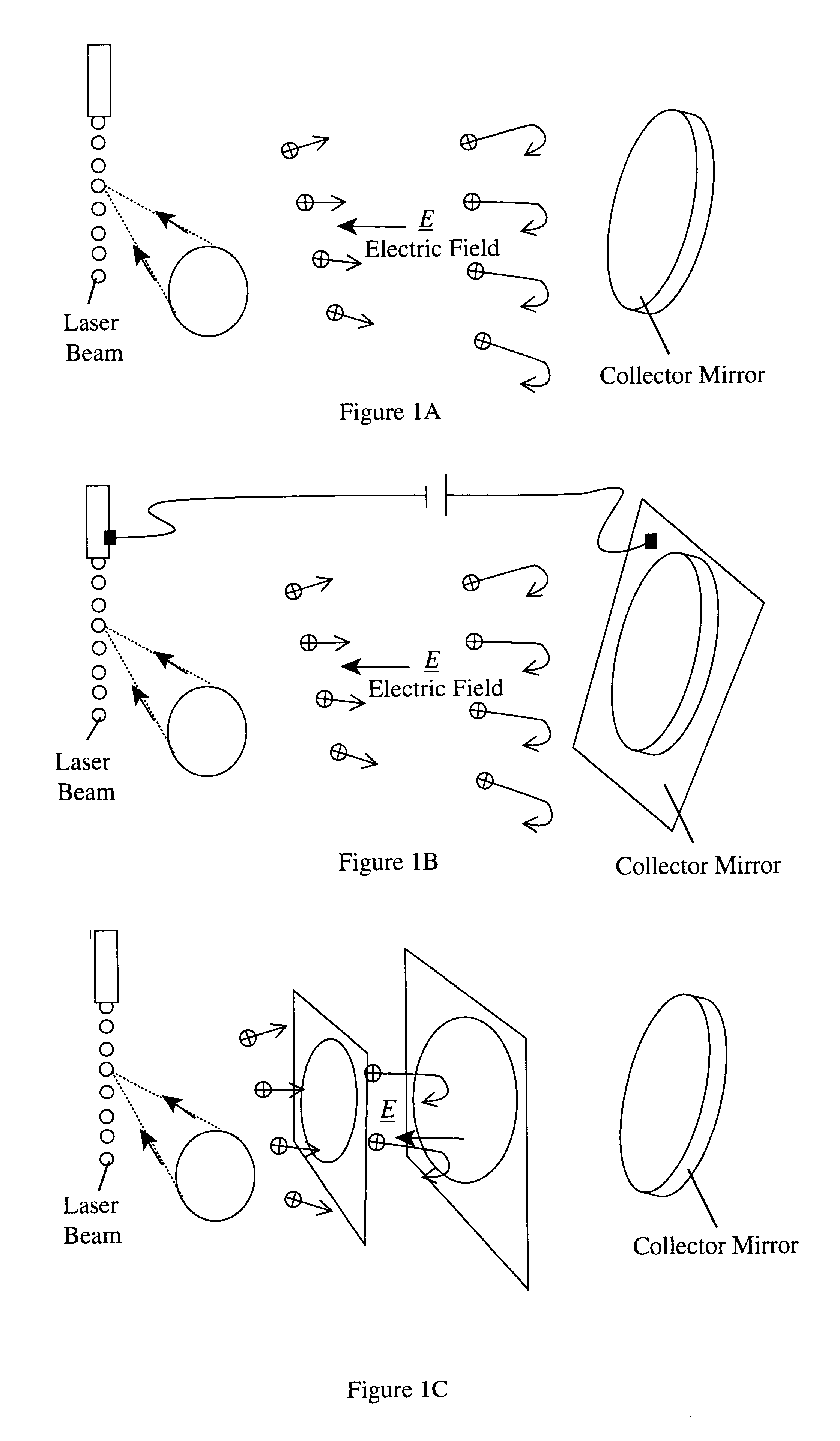
Before explaining the disclosed embodiment of the present invention in detail, it is to be understood that the invention is not limited in its application to the details of the particular arrangement shown since the invention is capable of other embodiments. Also, the terminology used herein is for the purpose of description and not of limitation. The substance of this invention which provides for a marked increase in the operational lifetime of EUV lasers in the production of lithographs is the introduction of an auxiliary electrode system which provides a repeller field that slows down and reverses the trajectory of ions from the laser beam source before they impact the collection mirror. The auxiliary electrode system can be of the form shown in FIG. 1 The general requirement of the ion repeller approach is that an electric field is inserted between the source of the ions and the collection mirror [FIG. 1a], sufficient to repel the initial trajectory of the ions. The application ...


PUM

PropertyMeasurementUnit
dc voltageaaaaaaaaaa
frequencyaaaaaaaaaa
wavelengthsaaaaaaaaaa

Abstract

A laser produced extreme ultraviolet (EUV) source based on a water droplet target has been implemented an auxiliary electrode system between the source and the first collector mirror. The auxiliary electrode system creates a repeller electric field, possibly a dc voltage imposed on the mirror that slows down and reverses the trajectories of ions from the source before they impact the collection mirror. The source modified according to the invention was evaluated with respect to the demands of EUV lithography and found to have much extended operational lifetimes. The spectral distribution of the generated radiation as well as the conversion efficiency into line radiation at 13 nm was determined. Long time measurements of the reflectivity of silicon/molybdenum multilayer mirrors for up to from 107 to 109 shots show the useful influence of the treatment of ions emitted from the source. Several methods of debris reduction were tested and discussed. Surface analysis of the treated multilayer mirrors of is presented. Long time measurements of the reflectivity of silicon/molybdenum multilayer mirrors for up to 109 shots show the advantage provided by this invention.

Description

BACKGROUND AND PRIOR ARTFor soft x-ray or EUV projection lithography there is a need for a high repetition-rate laser plasma source that can radiate at a specific wavelengths in the EUV part of the spectrum and capable of operating at approximately 1200 Hz. The wavelength of the EUV radiation must correspond to the peak reflectivity of the precision multilayer coated reflective optics utilized in this approach. At the present time the wavelengths of choice are 13 nm and 11.7 nm, but in the future other wavelengths may be preferable. This type of source should comprise a compact high repetition-rate laser and a renewable target system capable of operating for prolonged periods of time. For a production line facility, there would need to be uninterrupted system operation for periods of approximately 3 months. That is, uninterrupted operation for some 109 shots. To make the irradiation system cost effective, current system cost scenarios indicate the unit shot material cost must be in ...

Claims


Application Information

Patent Timeline
Patent Type & Authority Patents(United States)
IPC IPC(8): G03F7/20H05G2/00
CPCB82Y10/00H05G2/008H05G2/003G03F7/70033
Inventor RICHARDSON, MARTINSHRIEVER, GUIDO
Owner UNIV OF CENT FLORIDA RES FOUND INC
Why Eureka
Try Eureka