Plating pretreatment apparatus and plating treatment apparatus

a pretreatment apparatus and plating technology, applied in the direction of electrolysis components, manufacturing tools, electrolysis processes, etc., can solve the problems of affecting the wear resistance of the cylinder, the inability to apply plating pretreatment by electrolytic etching to the inside surface of the cylinder, and the unstable flow velocity of the pretreatment liquid between the cylinder bore inside surface and the cathod

Inactive Publication Date: 2002-05-07
SUZUKI MOTOR CORP
View PDF7 Cites 10 Cited by
  • Summary
  • Abstract
  • Description
  • Claims
  • Application Information

AI Technical Summary

Benefits of technology

According to the above-described plating pretreatment apparatus, since a plating pretreatment liquid flows at a uniform flow velocity in the object to be treated, uniform etching can be performed over the whole inside surface of the object to be treated, and adhesion of the plating film is improved, resulting in a decrease in poor adhesion.
Thereby, even in the case of a multi-cylinder engine, the temperature of the pretreatment liquid contained in each cylinder can be grasped, and by appropriately regulating the current value and the flow rate of pretreatment liquid according to the temperature, the liquid temperature can be kept constant. Therefore, there are no variations in etching amount between cylinders, and the adhesion of the plating film is improved, so that the present invention can also be applied to a multi-cylinder cylinder block.
According to the above-described plating treatment apparatus, since an anode-cathode distance between the outside surface of the anode and the inside surface of the outlet jig is made larger than an anode-cathode distance between the outside surface of the anode and the inside surface of the object to be treated, a buffering effect is produced in the outlet jig, so that the plating liquid flows uniformly in the object to be treated. Therefore, when high-speed plating is performed, a fault of plating such as burnt deposit can be restrained, and a shortened treatment time and a reduced treatment cost can be achieved.
If the insoluble anode is used, the anode-cathode distance can further be decreased, so that the plating treatment time can further be shortened. For example, when a cylinder block is used as the object to be treated, according to the present invention, the anode-cathode distance can be decreased to 1 to 5 mm, although the conventional anode-cathode distance needs to be 5 mm and larger.
As described above, according to the plating pretreatment apparatus in accordance with the present invention, a buffering effect is produced by the lower void formed in the fixing jig, so that the plating pretreatment liquid flows uniformly in the object to be treated. Therefore, when high-speed plating is performed, a fault of plating such as burnt deposit can be restrained, and a shortened treatment time and a reduced treatment cost can be achieved.
On the other hand, according to the plating treatment apparatus in accordance with the present invention, a buffering effect is produced in the outlet jig, so that the plating liquid flows uniformly in the object to be treated. Therefore, when high-speed plating is performed, a fault of plating such as burnt deposit can be restrained, and a shortened treatment time and a reduced treatment cost can be achieved.

Problems solved by technology

However, when pretreatment is given to the inside surface of a cylindrical object to be treated such as a cylinder block, the flow velocity of pretreatment liquid between the cylinder bore inside surface and a cathode is unstable, so that the flow rate, one of the above-described condition values, is nonuniform.
Therefore, it has so far been difficult to apply plating pretreatment by means of electrolytic etching to a cylinder block.
For example, in the case where SiC is deposited in a form of Ni--P--SiC or Ni--SiC as the plating film, if the flow of plating liquid is nonuniform, the deposition of SiC is also nonuniform, so that a problem in regard to wear resistance of the cylinder occurs.
Also, at a high current density, abnormal deposition of the plating film called "burnt deposit" may occur in a portion where the plating liquid flows slowly.
Also, if the anode-cathode distance between the electrode and the object to be treated is short, the flow of plating liquid in a gap between the object to be treated and the anode is liable to be nonuniform, so that a fault of plating film such as burnt deposit develops, and therefore good plating treatment cannot be done.
Therefore, good plating treatment cannot be done.
An adverse influence caused by nonuniform flow of plating liquid arises more easily as the anode-cathode distance, that is, the distance between the anode and the inside surface of the object to be treated is decreased.
However, this prior art is still insufficient to be used for high-speed plating, and further uniformity of plating liquid flow is demanded.
According to the above-described plating pretreatment apparatus, since a plating pretreatment liquid flows at a uniform flow velocity in the object to be treated, uniform etching can be performed over the whole inside surface of the object to be treated, and adhesion of the plating film is improved, resulting in a decrease in poor adhesion.

Method used


Image

  • Plating pretreatment apparatus and plating treatment apparatus
  • Plating pretreatment apparatus and plating treatment apparatus
  • Plating pretreatment apparatus and plating treatment apparatus

Examples


example 1

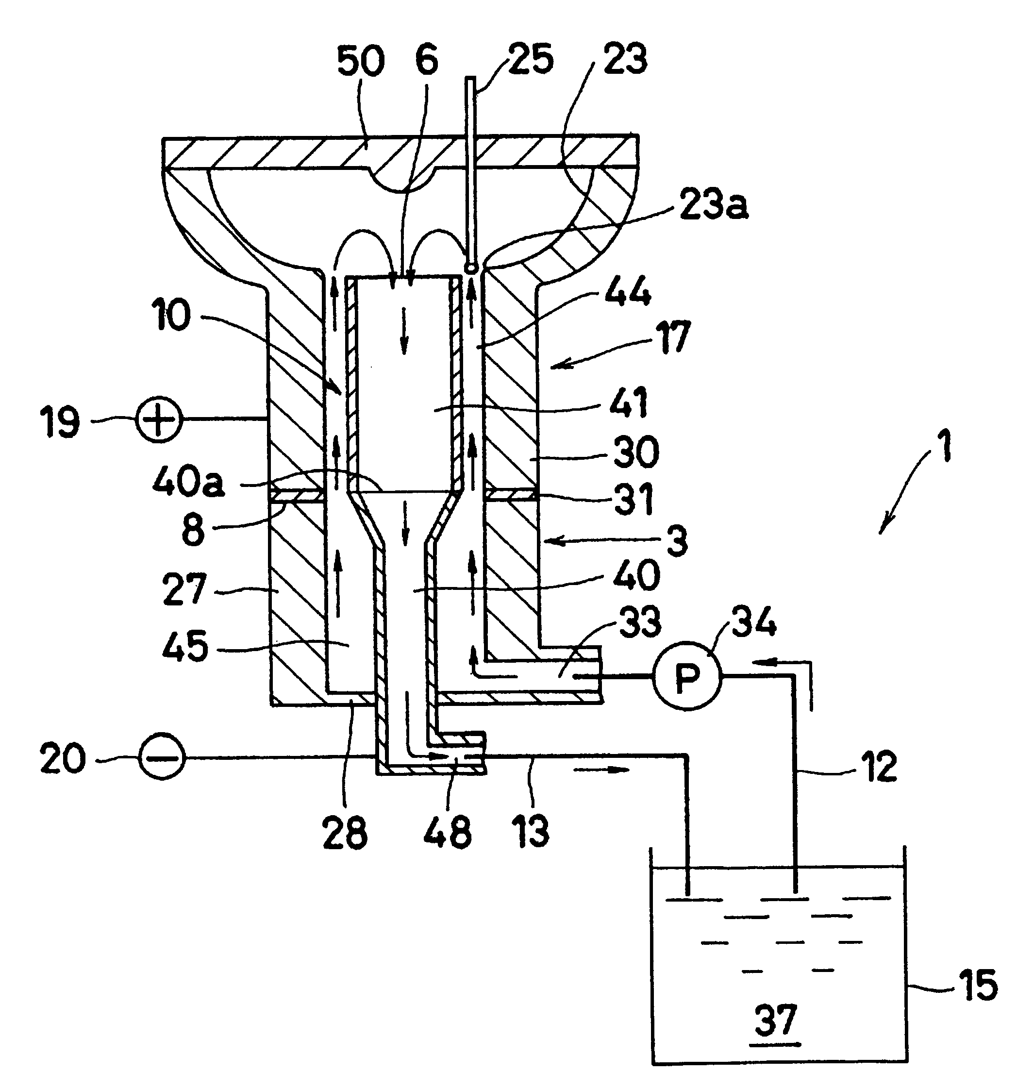
After plating pretreatment was given to the inside surface of the cylinder block 17 by using the plating pretreatment apparatus 1 shown in FIG. 1, plating treatment was done by using a not illustrated plating treatment apparatus. The cathode 10 disposed in the plating pretreatment apparatus 1 is composed of the cylindrical upper cathode 41 and the lower cathode 40 having a smaller diameter than the upper cathode 41 as described above, and these upper and lower cathodes 41 and 40 can be separated from each other.

Regarding the conditions of the plating pretreatment liquid 37, the flow rate was 10 liter / minute, the concentration of phosphoric acid was 300 g / liter, and the liquid temperature was 65.degree. C. Also, the density of current caused to flow between the cathode 10 and the cylinder block 17 was 50 A / dm.sup.2. The thermometer 25 was arranged in each cylinder of the cylinder block 17. Pretreatment was given to the inside surface of the cylinder block 17 while appropriately regul...

example 2

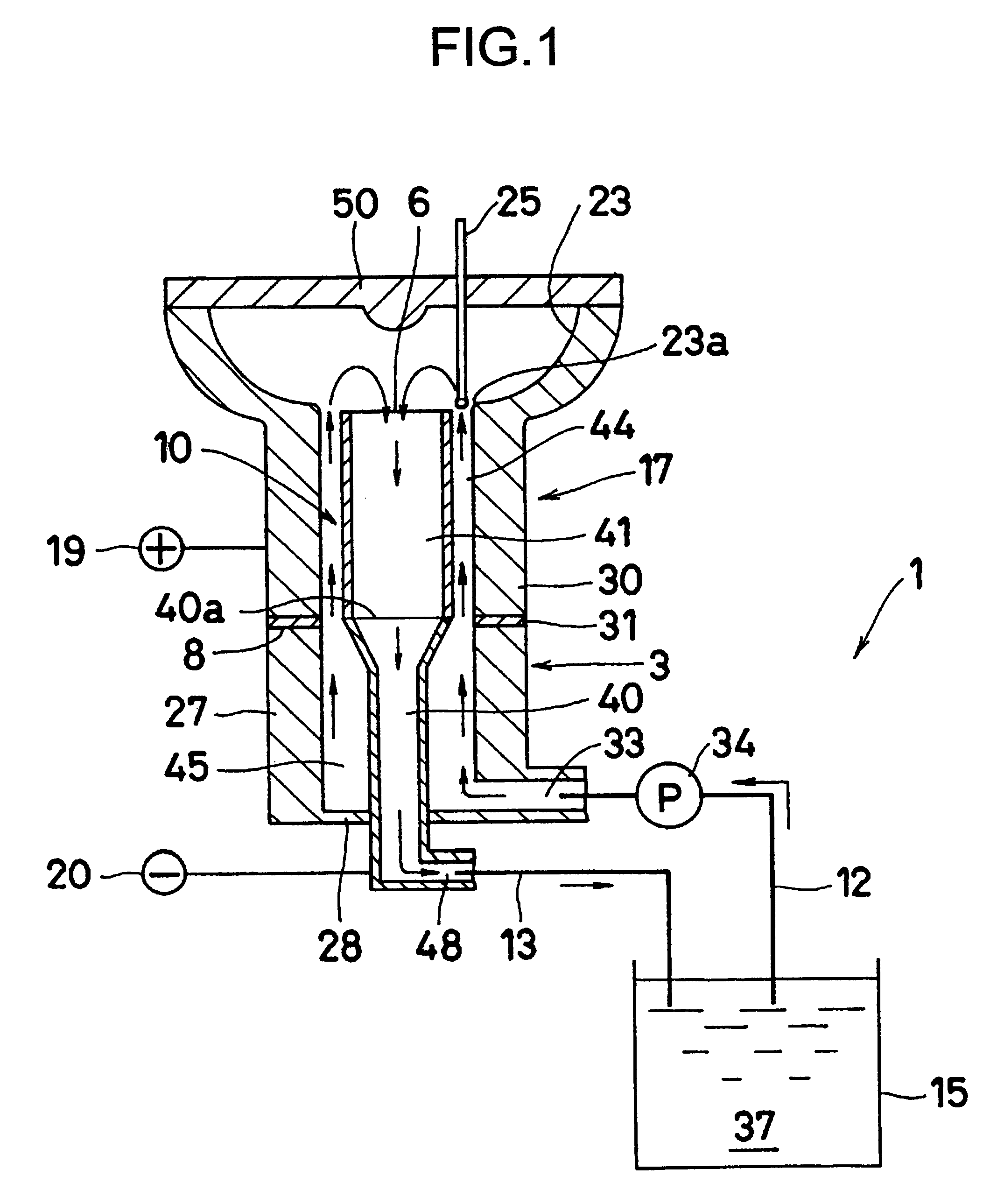
The inside surface of the cylinder block 117 was plated at various current densities by using plating treatment apparatuses 101 and 151 shown in FIGS. 2 and 3, respectively. As described above, FIG. 2 shows the plating treatment apparatus 101 having the lower anode 130 with a smaller diameter than that of the upper anode 131.

Contrarily, as a comparative example, a plating treatment apparatus 151 having a lower anode 153 with almost the same diameter as that of the upper anode 131 is shown in FIG. 3. All the construction of the plating treatment apparatus 151 shown in FIG. 3 is the same as that of the plating treatment apparatus 101 shown in FIG. 2 except for the lower anode 153.

Regarding the plating treatment conditions, the average flow velocity of the plating liquid 138 in both of the apparatuses 101 and 151 was kept constant, being 1.7 m / s, and all of the anode-cathode distance of the upper anode 131 in the apparatus 101 shown in FIG. 2 and the anode-cathode distances of the uppe...

example 3

Next, the cylinder block 117 was plated by using the anode in the shape shown in FIG. 2 and by changing only the anode to an insoluble anode or a titanium basket. Regarding the treatment conditions of plating treatment, the average flow velocity of the plating liquid 138 in both cases was kept constant, being 1.7 m / s. The result is given in Table 2.

In the case of the insoluble anode, no fault of plating such as burnt deposit occurred, and satisfactory plating treatment could be done at any current density of 100 to 150 (A / dm.sup.2). However, in the case of titanium basket, a fault of plating such as burnt deposit occurred at current densities of 120 to 150 (A / dm.sup.2). Also, since the outer peripheral surface of the titanium basket is formed into a wavy shape and therefore the dimensional accuracy is poor, a small anode-cathode distance may cause short-circuit between the anode and the object to be treated. Therefore, the anode-cathode distance must be larger than 5 mm.

The present ...


PUM

PropertyMeasurementUnit
diametersaaaaaaaaaa
diametersaaaaaaaaaa
current densityaaaaaaaaaa

Abstract

The present invention provides a plating pretreatment apparatus that includes a cylindrical cathode disposed in a hollow portion of a fixing jig. A cylindrical object to be treated is installed on the fixing jig so that the cathode is also arranged therein. A lower portion of the cathode has a smaller diameter than an upper portion thereof. The invention also provides a plating treatment apparatus that includes an outlet jig having a hollow portion for installing a cylindrical object to be treated on a top face thereof, a cylindrical anode disposed therein so that a top end thereof projects from the top face of the outlet jig, and a plating liquid tank connected to the anode and the outlet jig. A lower portion of the anode has a smaller diameter than an upper portion thereof.

Description

1. Field of the InventionThe present invention relates to a plating pretreatment apparatus used when plating treatment is given to the inner peripheral surface of an object to be treated formed into a cylindrical shape such as a cylinder block, and also relates to a plating treatment apparatus used when high-speed plating treatment is given to the inner peripheral surface of an object to be treated formed into a cylindrical shape such as a cylinder block.2. Description of the Related ArtUsually, before plating is performed, plating pretreatment is done, for example, by electrolytic etching to improve the adhesion of a plating film to a base material. In the pretreatment by means of electrolytic etching, as the condition values of liquid temperature, flow rate, and electric current amount increase, the etching amount increases.As one example of the conventional electrolytic etching, a method for plating pretreatment in which electrolytic etching is performed in a pretreatment liquid ...

Claims


Application Information

Patent Timeline
Patent Type & Authority Patents(United States)
IPC IPC(8): C25D7/04C25F7/00
CPCC25F7/00C25D7/04
Inventor KURODA, TETSUYAKATO, HIDEZUMI
Owner SUZUKI MOTOR CORP
Why Eureka
Try Eureka