Regulated low-voltage generation circuit

a low-voltage generation and circuit technology, applied in the direction of electric variable regulation, process and machine control, instruments, etc., can solve the problems of power consumption, inability to control the voltage reference,

Inactive Publication Date: 2002-05-07
RENESAS ELECTRONICS AMERICA
View PDF8 Cites 41 Cited by
  • Summary
  • Abstract
  • Description
  • Claims
  • Application Information

AI Technical Summary

Problems solved by technology

Additionally, the voltage reference is largely insensitive to semiconductor processing variations.
However, the bandgap voltage reference circuit that is described above imposes an inherent design constraint that has become increasingly less tolerable as system designs have evolved.
Although prior-art integrated circuit design and fabrication techniques have enabled operation from voltage sources as low as 1.5V, state-of-the-art designs are expected to be driven by power consumption and dissipation considerations to voltage sources as low as 1.2V, or even 1.0V.

Method used


Image

  • Regulated low-voltage generation circuit
  • Regulated low-voltage generation circuit
  • Regulated low-voltage generation circuit

Examples


Embodiment Construction

)

For a thorough understanding of the subject invention, reference is made to the following Description, which includes the appended Claims, in connection with the above-described Drawings.

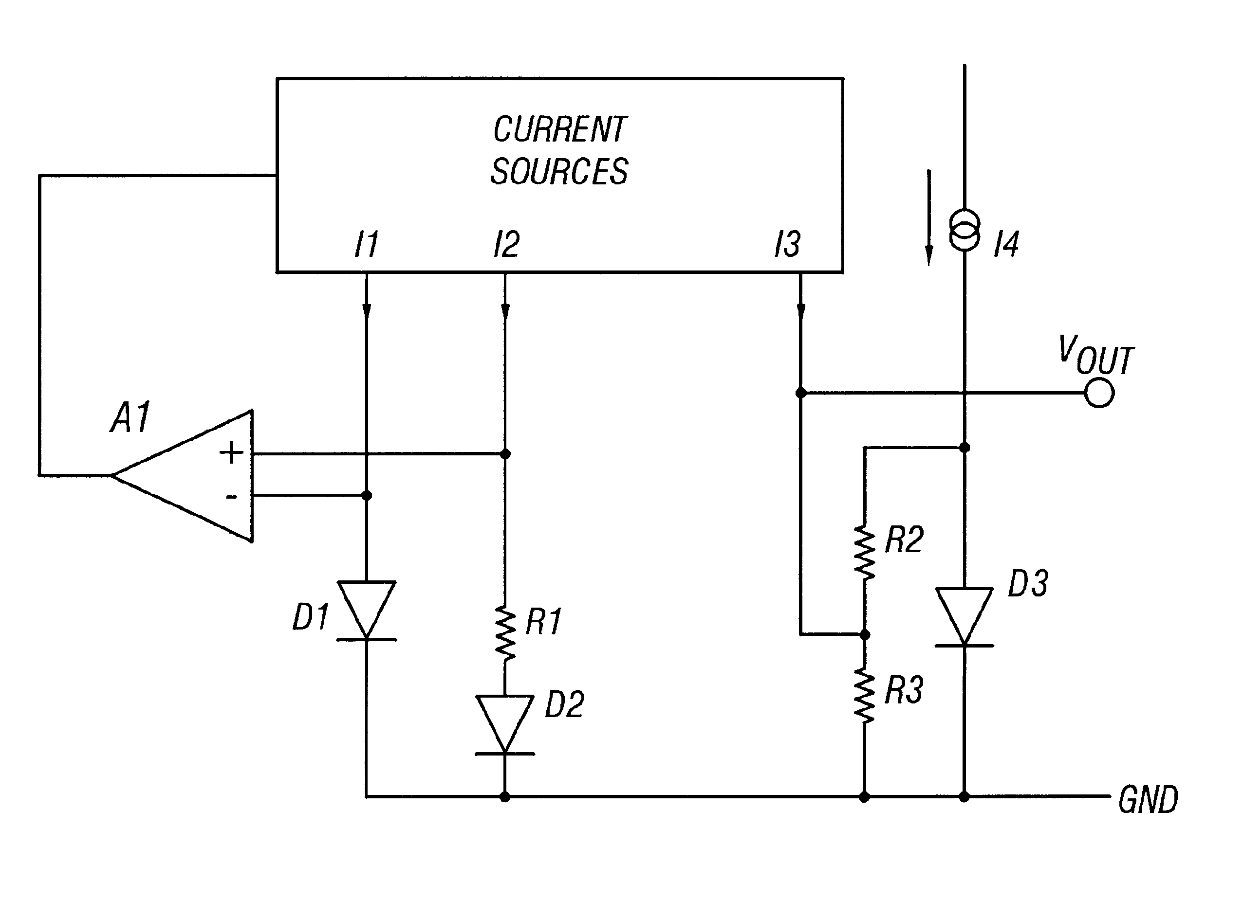
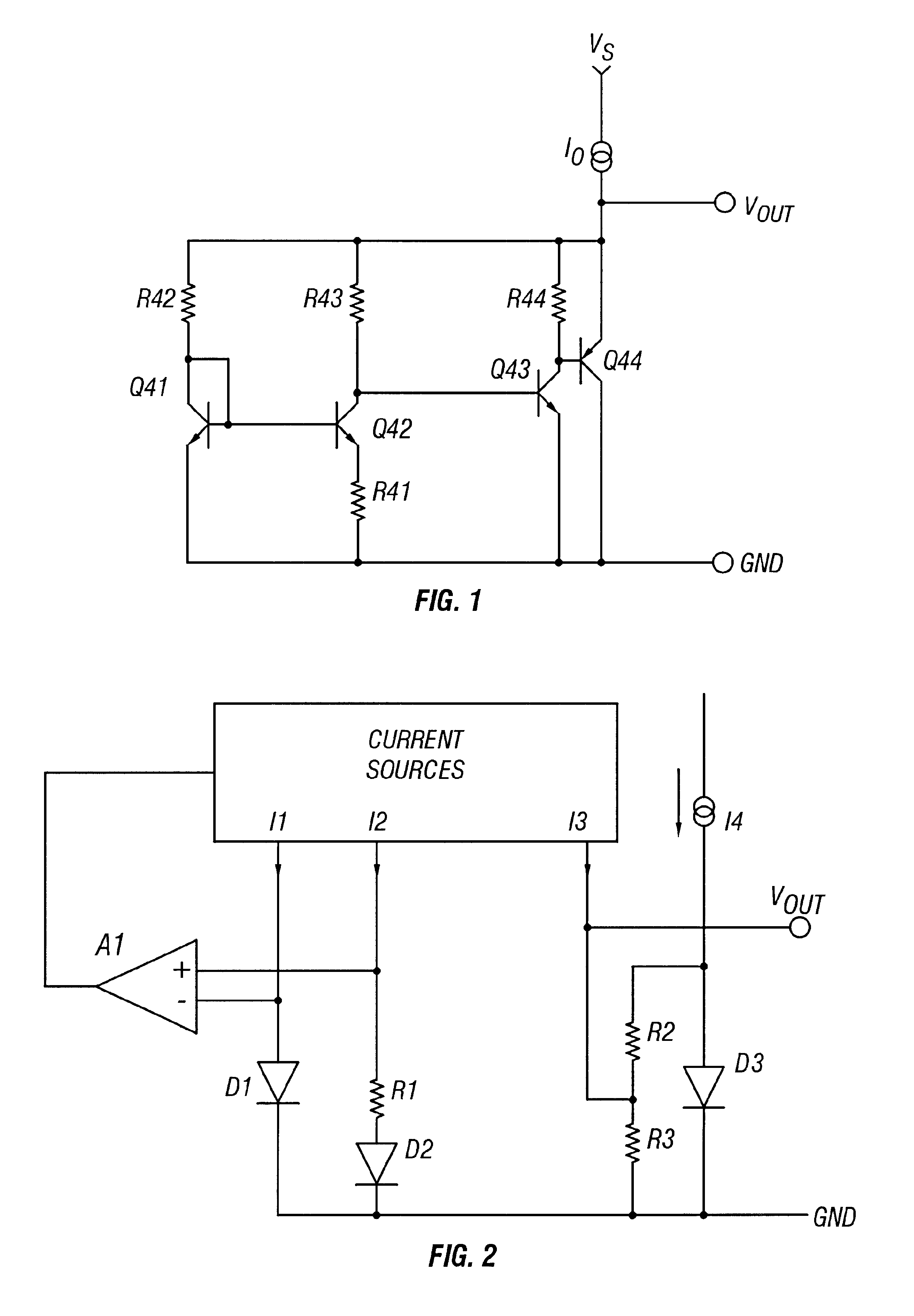
Referring now to FIG. 2, which is a circuit diagram of a preferred embodiment of the invention, the invention can be seen to include a bank of current sources I1, I2 and I3, each supplying respective currents of equal value. I1 is coupled to the inverting input of an operational amplifier A1 and through diode D1 to GND. I2 is coupled to the noninverting input of A1 and through the series combination of resistor R1 and diode D2 to GND. I3 is coupled to a resistor R3 to GND and through a resistor R4 to a fourth current source I4. I4 is also coupled through a diode D3 to GND. Operation of the bandgap voltage reference circuit depicted in FIG. 2 may be understood with the assumption that the following conditions apply: (1) current sources I1, I2 and I3 supply currents of equal value; (2) the values of ...


PUM


Abstract

A voltage reference generating circuit for providing voltage references substantially less than the typical 1300 mV, with a controllable thermal coefficient. By forcing equal-valued currents through two semiconductor junctions having disparate junction areas, a voltage differential is developed, as is a current proportional to the voltage differential. The voltage differential, and a current proportional to the voltage differential, have positive thermal coefficients. A third semiconductor junction is biased from a third current source and bridged by a resistor pair so as to synthesize a Thevenin-equivalent voltage equivalent series resistance. The equivalent voltage has a negative thermal coefficient. By forcing a current that is equal to the proportional current through the equivalent resistance, a reference voltage, equal to the sum of the Thevenin-equivalent voltage plus the voltage drop across the Thevenin-equivalent resistance, is created.

Description

1. Field of the InventionThis invention relates to the design and fabrication of integrated circuit devices and, more particularly, to the design of a low-voltage reference generation circuit that provides low reference voltage with a controllable thermal coefficient.2. Description of the Related ArtAs is well known, bandgap voltage reference circuits are commonly deployed in the design of integrated circuit devices. The advantages associated with bandgap voltage reference circuits largely derive from the fact that such circuits are capable of providing a thermally stable voltage reference. In practice, the thermal coefficient of the voltage reference ideally approaches zero. An analysis of a number of embodiments of bandgap voltage reference circuits may be found in the textbook "Analog Integrated Circuit Design", by David A. Jones and Ken Martin (John Wiley & Sons), pp. 353-364, which is hereby incorporated by reference.FIG. 1 depicts a bandgap voltage reference circuit that is co...

Claims


Application Information

Patent Timeline
Patent Type & Authority Patents(United States)
IPC IPC(8): G05F3/22G05F3/08G05F3/26G05F1/10
CPCG05F3/265G05F3/225
Inventor SUGAWARA, MITSUTOSHI
Owner RENESAS ELECTRONICS AMERICA
Why Eureka
Try Eureka