Level shifter

Inactive Publication Date: 2002-05-07
SEMICON ENERGY LAB CO LTD
View PDF9 Cites 65 Cited by
  • Summary
  • Abstract
  • Description
  • Claims
  • Application Information

AI Technical Summary

Problems solved by technology

However, as the difference between the voltage amplitudes becomes large, it becomes more difficult for the level shifter to perform level conversion, resulting in the occurrence of p

Method used


Image

  • Level shifter
  • Level shifter
  • Level shifter

Examples


embodiment 1

[Embodiment 1]

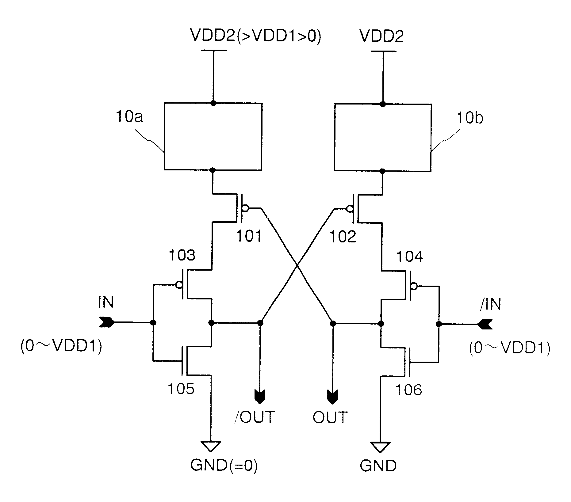
A level shifter shown in FIG. 5 which shifts the high electric potential side of a signal with the low electric potential side thereof fixed will be explained in Embodiment 1. It is to be noted that Embodiment 1 is an embodiment which specifies concrete examples of the voltage regulating circuits with respect to Embodiment Mode 1. In addition, the level shifter of Embodiment 1 is a reformed type of the conventional example shown in FIG. 23, and hence the same reference symbols are used for the transistors and the like corresponding to the respective parts. The structure of the level shifter of Embodiment 1 is as follows. A source of a PMOST 113 and a source of a PMOST 114 are each connected to the power source VDD2, and a gate and a drain of the PMOST 113 are connected to the source of the PMOST 101 while a gate and a drain of the PMOST 114 are connected to the source of the PMOST 102, respectively. The drain of the PMOST 101 is connected to the source of the PMOST 103...

embodiment 2

[Embodiment 2]

An example of a different level shifter which shifts the high electric potential side of a signal with the low electric potential side thereof fixed will also be explained in Embodiment 2. As shown in FIG. 8, the level shifter of Embodiment 2 is one in which the PMOST 113 and 114 in the level shifter of Embodiment 1 are replaced by NMOST 115 and 116, respectively, and the gates thereof are connected to the power source VDD2. It is to be noted that Embodiment 2 is also an embodiment which specifies concrete examples of the voltage regulating circuits with respect to Embodiment Mode 1. In addition, the level shifter of Embodiment 2 is a reformed type of the exemplified conventional level shifter shown in FIG. 23, and hence the same reference symbols are used for the transistors corresponding to the respective parts.

The structure of the level shifter of Embodiment 2 is as follows. A drain and a gate of the NMOST 115 and a drain and a gate of the NMOST 116 are each connect...

embodiment 3

[Embodiment 3]

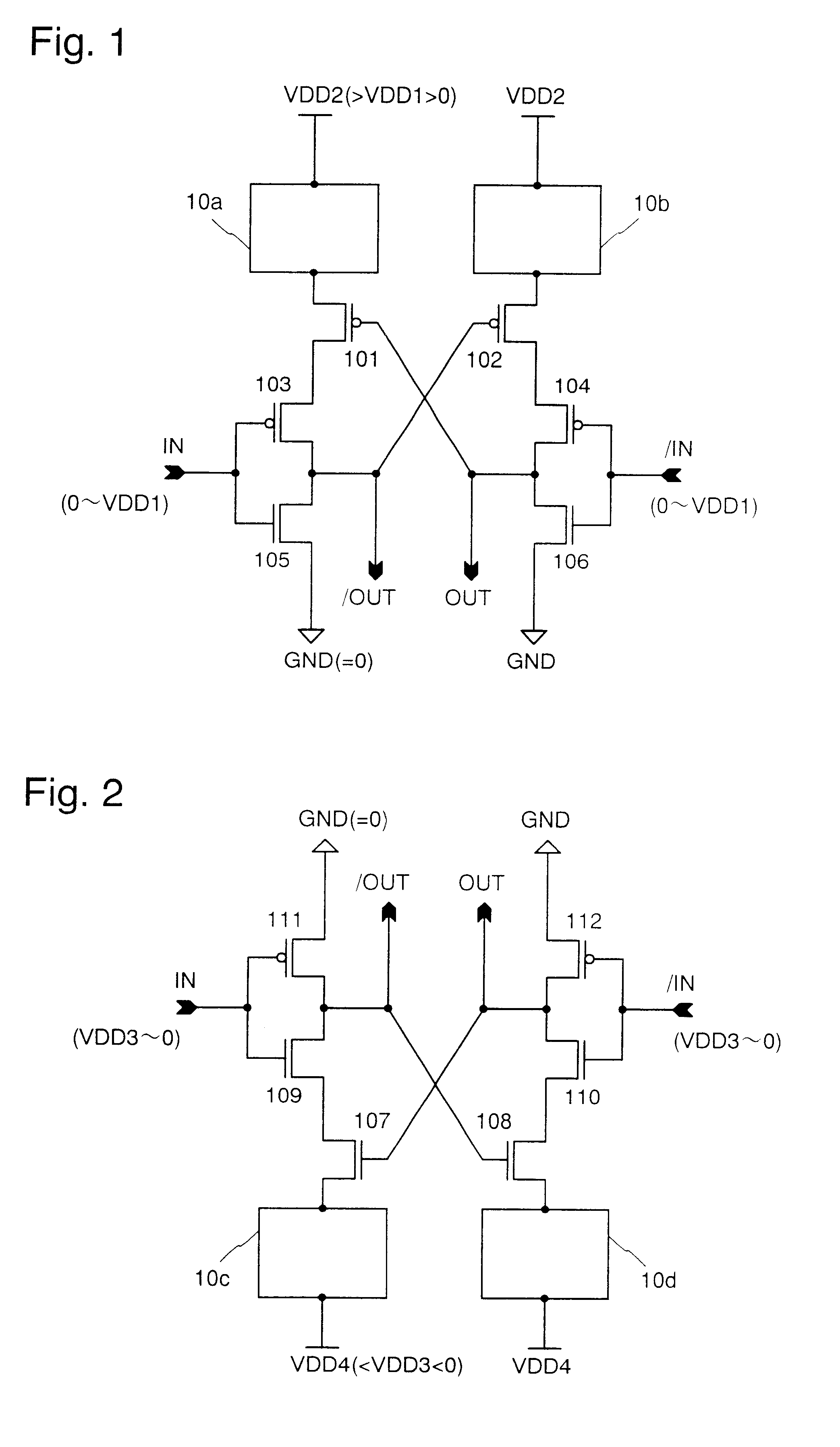
A level shifter shown in FIG. 9 which shifts the low electric potential side of a signal with the high electric potential side thereof fixed will be explained in Embodiment 3. It is to be noted that Embodiment 3 is an embodiment which specifies concrete examples of the voltage regulating circuits with respect to Embodiment Mode 2. In addition, the level shifter of Embodiment 3 is a reformed type of the exemplified conventional level shifter shown in FIG. 24, and hence the same reference symbols are used for denoting the transistors and the like corresponding to the respective parts.

The structure of the level shifter of Embodiment 3 is as follows. A source of an NMOST 117 and a source of an NMOST 118 are each connected to the power source VDD4, and a gate and a drain of the NMOST 117 are connected to the source of the NMOST 107 while a gate and a drain of the NMOST 118 are connected to the source of the NMOST 108, respectively. The drain of the NMOST 107 is connected to...


PUM


Abstract

A compact level shifter is provided, which has a low consumption power and speedy operation, capable of easily performing a level conversion of voltage levels having a large difference. A voltage regulating circuit (10a), a P channel MOS electric field effect transistor (hereinafter referred to as PMOST), a PMOST (103), and an N channel MOS electric field effect transistor (hereinafter referred to as NMOST) (105) are connected in series between 2 power sources. Similarly, a voltage regulating circuit (10b), a PMOST (102), a PMOST (104), and an NMOST (106) are connected in series between 2 power sources. During the flow of a penetrating current in a transient period of a level conversion operation, a power source voltage is effectively reduced by the above-mentioned voltage regulating circuit, whereby the level conversion of the voltage level having a large difference is made easy.

Description

1. Field of the InventionThe present invention relates to a level shifter that is employed in a driver circuit of an image display device (active matrix image display device) for displaying information such as an image by means of switching elements and pixels arranged in matrix.2. Description of the Related ArtIn recent years, the fining of a technique in manufacturing semiconductors is advancing. Further, because of the popularized electronic equipment such as a portable equipment which demands low consumption power, the LSI that is used in these equipments has become 3.3 V, that is, a 3.3 V low power source voltage drive has become the mainstream. On the other hand, in a liquid crystal display, which is recently in high demand for its use as a monitor of a portable terminal, computer, etc., a liquid crystal drive is conducted by a 10 to 20 V of voltage amplitude signal. Thus, it has become necessary to provide at least a circuit portion that operates at a high power source voltag...

Claims


Application Information

Patent Timeline
IPC IPC(8): H03K19/00H03K19/0185G02F1/133G09G3/20G09G3/30G09G3/36H03K3/356H04N5/66
CPCH03K19/018521H03K19/0013H03K3/356G09G3/3688G09G2310/0289
Inventor AZAMI, MUNEHIRO
Owner SEMICON ENERGY LAB CO LTD
Why Eureka
Try Eureka