Tunable birdcage transmitter coil

a transmitter coil and bird cage technology, applied in the field of magnetic resonance arts, can solve the problems of increasing the risk of local heating in the end-ring capacitor, significant increment, and difficulty in tuning the coil to the desired frequency, so as to achieve convenient varying of both capacitance and inductance of the rf coil, a wider tuning range, and higher power radio frequency pulses

Inactive Publication Date: 2002-05-28
PICKER INT
View PDF11 Cites 93 Cited by
  • Summary
  • Abstract
  • Description
  • Claims
  • Application Information

AI Technical Summary

Benefits of technology

One advantage of the present invention is that it conveniently varies both capacitance and inductance of the RF coil.
is that it conveniently varies both capacitance and inductance of the RF coil.
Another advantage of the present invention is that it provides a wider tuning range.
Another advantage of the present invention is that a birdcage coil can be tuned to higher frequencies and used in higher magnetic fields and for higher power radio frequency pulses.
Still further advantages and benefits of the present invention will become apparent to those of ordinary skill in the art upon reading and understanding the following detailed description of the preferred embodiments.

Problems solved by technology

As transmit coils are used in higher magnetic fields and at higher power, there is an increased risk of local heating in the end-ring capacitors due to higher voltages and currents.
While the additional capacitors aid in the lowering of voltage and the reduction of capacitor heating, tuning the coil to desired frequencies becomes problematic due to the cumulative large capacitance values at many positions on the coil.
It is difficult to make a significant increment in capacitance with physically small capacitors, which in turn, diminishes the range over which the coil may be tuned.
Again, the existence of large values of capacitance at many positions on the coil makes it difficult to adjust capacitance with physically small capacitors.
In addition, in a 3.0 Tesla B.sub.0 magnetic field, hydrogen dipoles have a resonant frequency of 128 MHZ, which poses even further tuning problems.

Method used


Image

  • Tunable birdcage transmitter coil
  • Tunable birdcage transmitter coil
  • Tunable birdcage transmitter coil

Examples


Embodiment Construction

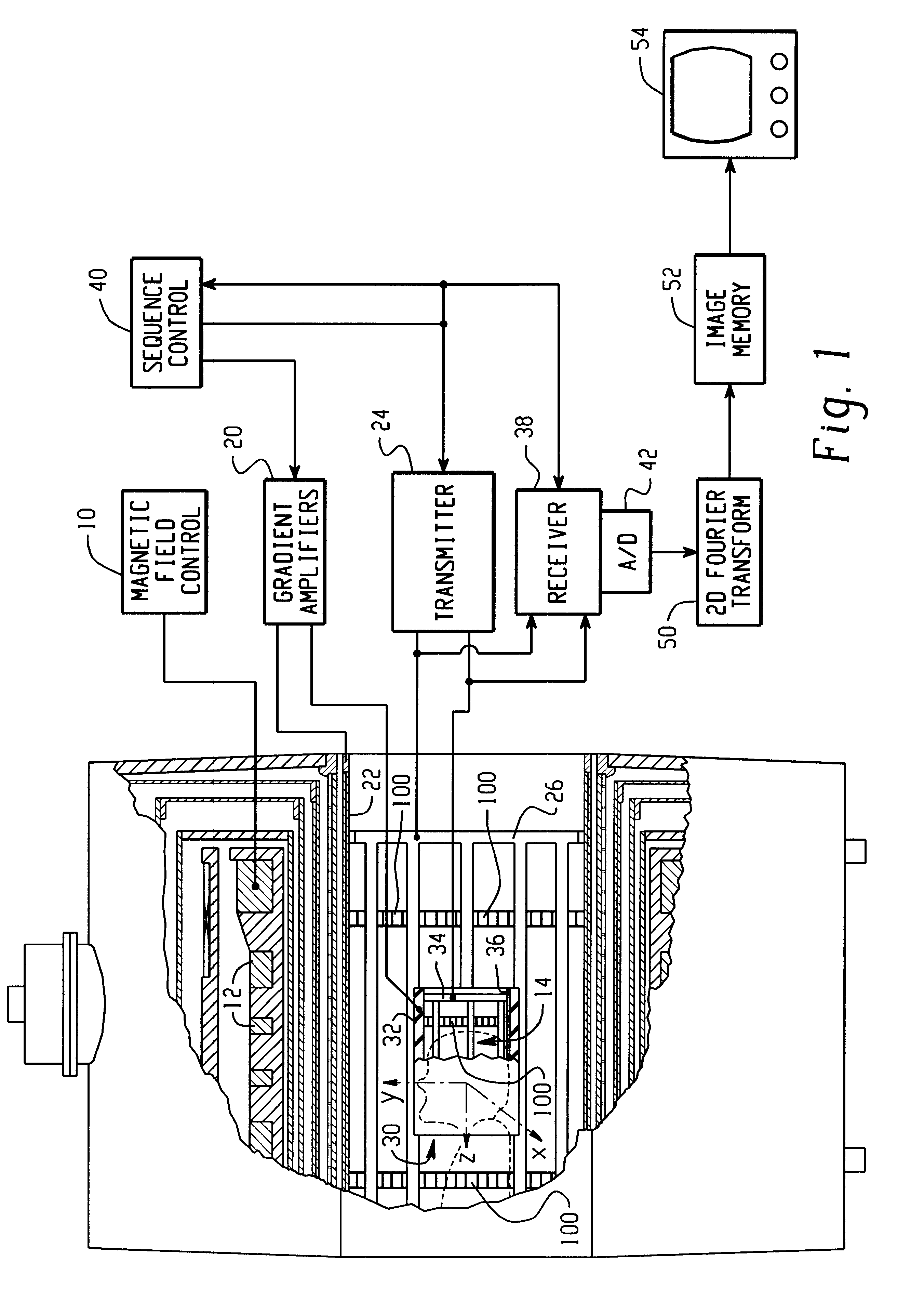
With reference to FIG. 1, a main magnetic field control 10 controls superconducting or resistive magnets 12 such that a substantially uniform, temporally constant main magnetic field B.sub.0 is created along a z-axis through an examination region 14. Although a bore-type magnet is illustrated in FIG. 1, it is to be appreciated that the present invention is equally applicable to open magnetic systems. A magnetic resonance sequence applies a series of radio frequency (RF) and magnetic field gradient pulses to invert or excite magnetic spins, induce magnetic resonance, refocus magnetic resonance, manipulate magnetic resonance, spatially and otherwise encode the magnetic resonance, to saturate spins, and the like to generate magnetic resonance imaging and spectroscopy sequences. More specifically, gradient pulse amplifiers 20 apply current pulses to selected ones or pairs of whole body gradient coils 22 to create magnetic field gradients along x, y and z-axes of the examination region 1...


PUM


Abstract

A tunable radio frequency birdcage coil (26, 34) has an improved tuning range for use with a magnetic resonance apparatus. The coil includes a pair of end ring conductors (60, 62) which are connected by a plurality of spaced leg conductors (L2, L4, . . ., L26) to form a generally cylindrical volume. Both the end rings and the leg conductors contain reactive elements, preferably capacitors (C2, C4, . . ., C124). The radio frequency coil also includes a pair of tuning rings (100, 120) for tuning the reactive elements (C2, C4, . . ., C124), which each include a non-conductive support cylinder (110, 130) and a plurality of tuning bands (120, 122, . . ., 142 and 150, 152, . . ., 172) which extend axially along the outer surface of the support cylinder (110, 130). The tuning rings (100, 120) are rotated or translated with respect to the leg conductors (L2, L4, . . ., L26) in order to vary capacitance and inductance of the coil (26, 34) to tune the (26, 34) coil to the desired resonant frequency.

Description

BACKGROUND OF THE INVENTIONThe present invention relates to the magnetic resonance arts. It finds particular application in conjunction with a radio frequency magnetic resonance coil which is tuned to the resonance frequencies of hydrogen (or other dipoles of interest) for anatomical, angiographic, functional and other medical imaging and will be described with particular reference thereto. It is to be appreciated, however, that the invention will also find application in animal studies, other non-human studies, spectroscopy, multiple dipole studies, very high field studies, multiple B.sub.0 field systems, phased-array coil techniques, and the like.Conventionally, magnetic resonance systems generate a strong, temporally constant static magnetic field, commonly denoted B.sub.0, in a free space or bore of a magnet. This main magnetic field polarizes the nuclear spin system of an object. Polarized dipoles of the object then possesses a macroscopic magnetic moment vector preferentially ...

Claims


Application Information

Patent Timeline
Patent Type & Authority Patents(United States)
IPC IPC(8): G01R33/34A61B5/055G01R33/36
CPCG01R33/34046
Inventor BURL, MICHAELGAUSS, ROBERT C.
Owner PICKER INT
Why Eureka
Try Eureka