Wide frequency range couplers and detectors for power detection in multiple frequency band systems

a technology of power detection and detectors, applied in the direction of transmission monitoring, gain control, substation equipment, etc., can solve the problems of increasing the cost, complexity, and size of dualband phones, and the capacity of base stations in highly populated areas can become saturated, so as to achieve optimal performance characteristics, accurate power measurement, and minimal insertion loss

Inactive Publication Date: 2002-05-28
SKYWORKS SOLUTIONS INC
View PDF9 Cites 52 Cited by
  • Summary
  • Abstract
  • Description
  • Claims
  • Application Information

AI Technical Summary

Benefits of technology

Thus, the inventor of the present invention has developed a wide frequency range power sensing device 34 capable of accurately measuring the power over a wide range of frequencies, while varying the parameters of the power sensing device 34 so that the insertion loss is optimized for the various transmission frequency bands. A directional coupler 36 h

Problems solved by technology

The capacity of base stations in highly populated areas can become saturated during time periods of high use.
Howev

Method used


Image

  • Wide frequency range couplers and detectors for power detection in multiple frequency band systems
  • Wide frequency range couplers and detectors for power detection in multiple frequency band systems
  • Wide frequency range couplers and detectors for power detection in multiple frequency band systems

Examples


Embodiment Construction

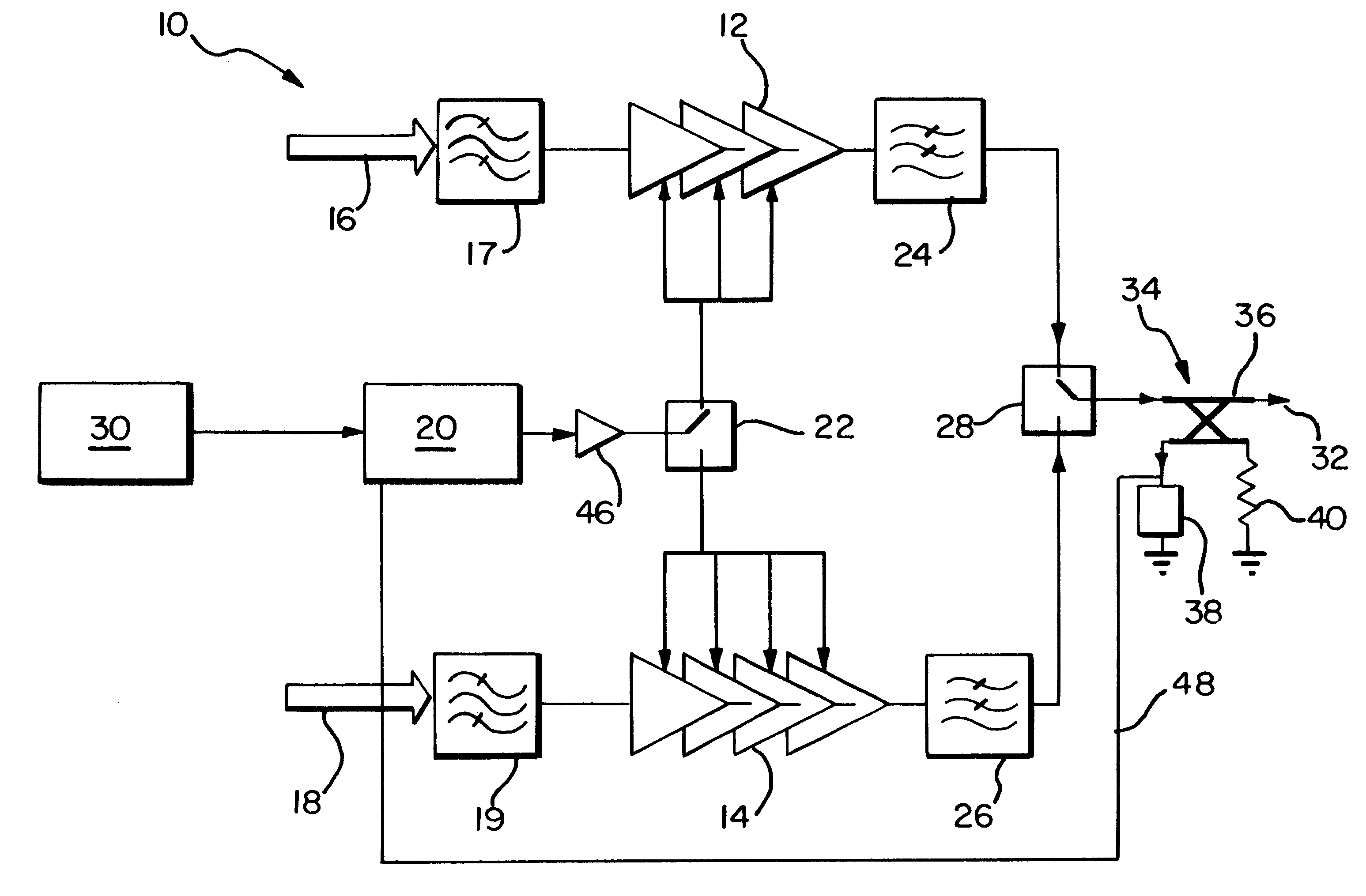
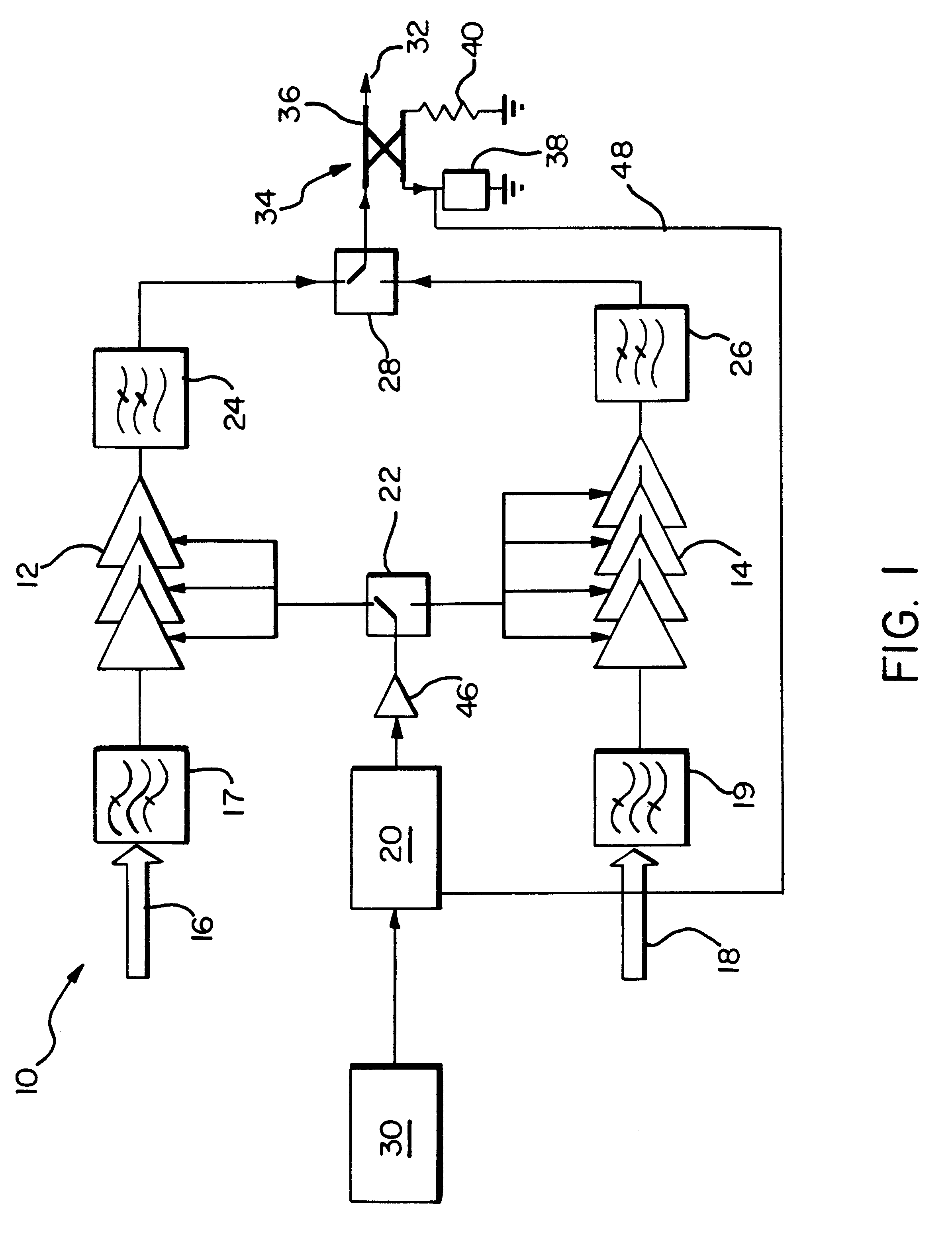
There are many types of transmission techniques currently being used for mobile telephones, where such digital transmission techniques include GSM (Global System for Mobile Communications) 900 and GSM 1800. GSM 900 operates at a frequency band of 900 MHz, while GSM 1800 operates at a frequency band of 1800 MHz. The multiband phone of the present invention could be designed to operate at both GSM 900 and GSM 1800 frequency bands. GSM 1800 has a bandwidth of 75 MHz as compared to 25 MHz for GSM 900, so that a GSM 1800 base station has three times the capacity of usable channels than GSM 900. However, the transmission distance of a GSM 1800 signal is much smaller than that of GSM 900, because the transmission frequency of GSM 1800 is twice that of GSM 900 and the power of the GSM 1800 transmitted signal is half that of GSM 900. Thus, a GSM 1800 base station covers a much smaller area than that of a GSM 900 base station.

Processing device 30 receives signals from the base stations of bot...


PUM


Abstract

A multiband phone capable of transmitting a signal within a plurality of distinct frequency bands having a single wide frequency range power detecting device capable of measuring the power of the transmitted signal over all of the plurality of frequency bands. The multiband phone includes multiple power amplifiers, where each power amplifier amplifies the power of a signal transmitted within a different frequency band. A power amplifier controller is provided for controlling the amount of amplification performed by the power amplifiers, where a switching device switches the connection of the power amplifier controller to a selected power amplifier. The single wide frequency range power detecting device is connected to the output of the all of the power amplifiers through a switching device, where the switching device connects the power detecting device to the particular power amplifier selected for transmission. The power detector then measures the power of the signal transmitted and feeds the measured power back to the power amplifier controller. The power amplifier controller may then adjust the voltage driving the power amplifier connected thereto based upon any difference detected between the desired output power and the measured output power. The performance of the wide frequency range power detecting device is adjusted for the specific transmission frequencies utilized by the multiband phone in order to achieve optimal power detection sensitivity over all of the multiple frequencies.

Description

1. Field of the InventionThe present invention relates generally to power detection in a multiple frequency band transmission system, and specifically to a single wide frequency range coupler and detector pair for detecting the transmitted power of a multiband telephone.2. Description of Related ArtMobile phones have recently gained widespread use throughout the world. Mobiles phones communicate with a base station serving a predetermined area or cell. Each base station has a limited bandwidth within which to operate, depending upon the particular transmission technique utilized by the base station. This limited bandwidth is separated into a plurality of channels frequency-spaced evenly from one another, where these channels are used by the mobile phones within that base station's transmission area. Each base station may only handle a limited number of phones equal to the number of channels and time-slots on those channels provided by that base station. Therefore, the frequency spac...

Claims


Application Information

Patent Timeline
IPC IPC(8): H03G3/30H04B1/40H04B1/04
CPCH03G3/3042H04B1/406H04B1/005H04B2001/0433H03F1/34H03F3/24
Inventor JENSEN, NIELS J.
Owner SKYWORKS SOLUTIONS INC
Why Eureka
Try Eureka