High power short arc discharge lamp with heat sink

a technology of short arc discharge and heat sink, which is applied in the direction of discharge tube/lamp details, discharge tube main electrodes, incadescent cooling arrangements, etc., can solve the problems of rapid electrode erosion, catastrophic failure, and exacerbate the problem of heat dissipation, so as to reduce the thickness of the reflector body and thermal efficiency. , the effect of reducing the thickness of the body

Inactive Publication Date: 2002-06-04
EXCELITAS TECH
View PDF10 Cites 34 Cited by
  • Summary
  • Abstract
  • Description
  • Claims
  • Application Information

AI Technical Summary

Benefits of technology

The invention results from the realization that a more thermally efficient high power short arc gas discharge lamp can be achieved using an electrical insulating reflector body having a concave internal reflective surface and a conical external surface which reduces the thickness of the body and placing an external, electrically isolated heat sink in conforming engagement with the conical surface proximate the gas discharge gap.
A high power short arc gas discharge lamp includes an electrically insulating reflector body having a concave internal reflector surface with a focal point. There is an anode and a cathode spaced from the anode to create an arc gap between them proximate the focal point. The reflector body has a conical external surface for reducing the thickness of the reflector body between the concave internal surface and the conical external surface. An external electrically isolated heat sink is mounted on the external conical surface proximate the arc gap.

Problems solved by technology

Conventional short arc lamps, using xenon, argon or other gases, produce a broad spectrum light of 200 nm to 1100 nm or more at 1 to 2 Kw using a curved, concave reflector such as a parabolic or elliptical shape surrounding the arc Substantial heat is generated by these devices and can cause rapid electrode erosion and even catastrophic failure.
The heat dissipation problem is exacerbated by the fact that neither the ceramic nor xenon or other gas are very good thermal conductors.

Method used


Image

  • High power short arc discharge lamp with heat sink
  • High power short arc discharge lamp with heat sink
  • High power short arc discharge lamp with heat sink

Examples


Embodiment Construction

Other objects, features and advantages will occur to those skilled in the art from the following description of a preferred embodiment and the accompanying drawings, in which:

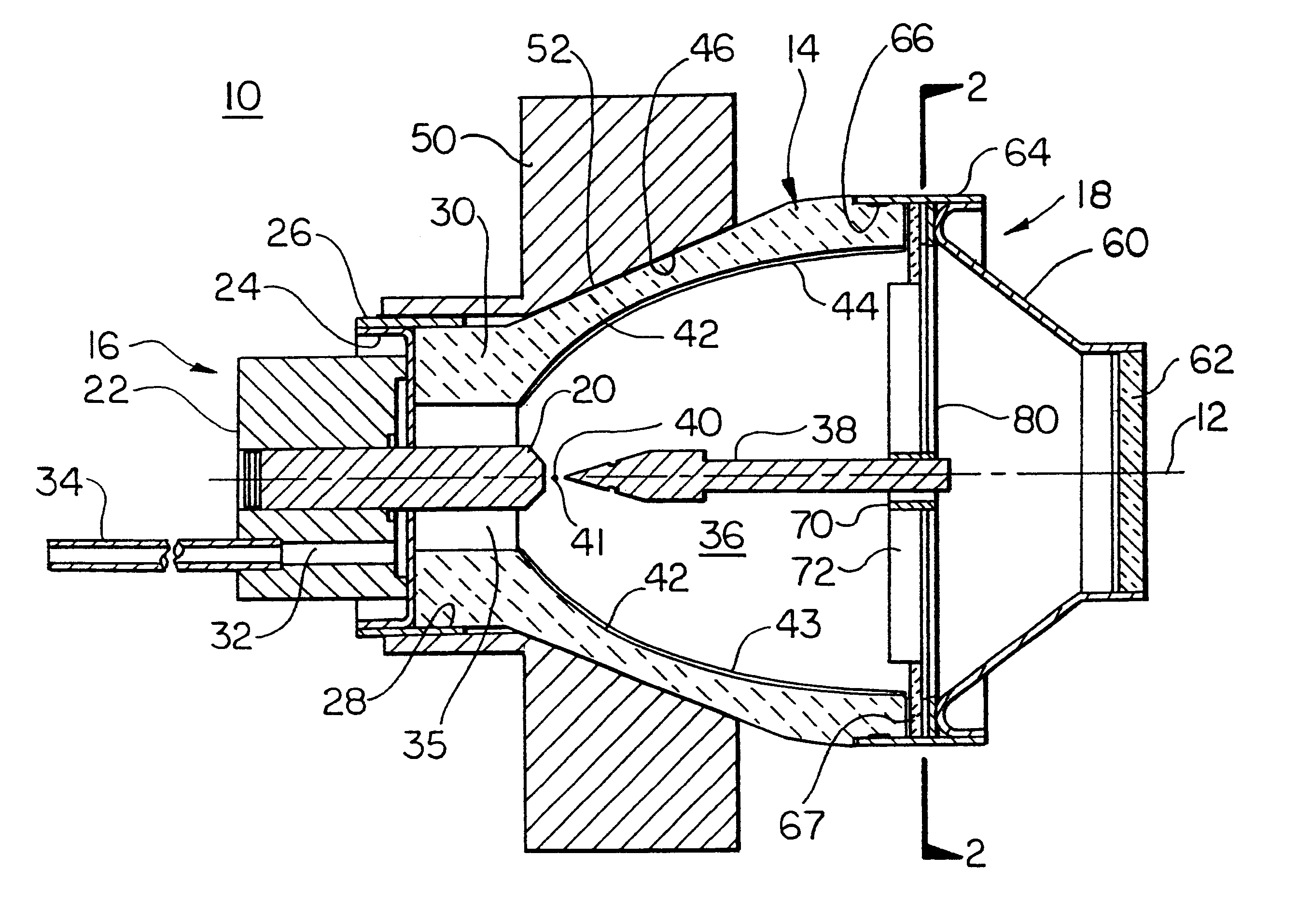
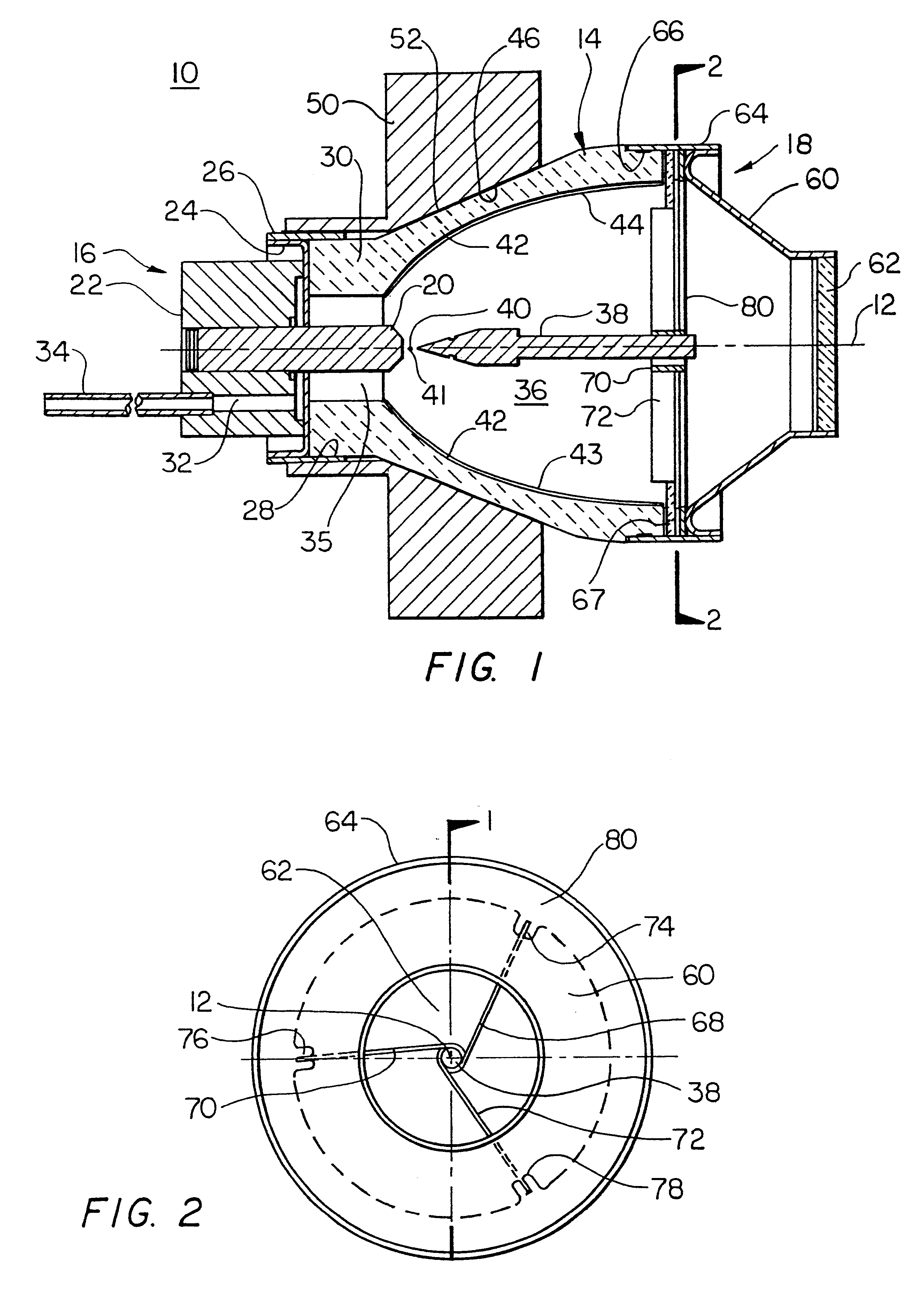
FIG. 1 is a side sectional view taken along lines 1--1 of FIG. 2. of a high power short arc circularly symmetrical gas discharge lamp according to this invention;

FIG. 2 is an end view of the lamp taken along line 2--2 of FIG. 1;

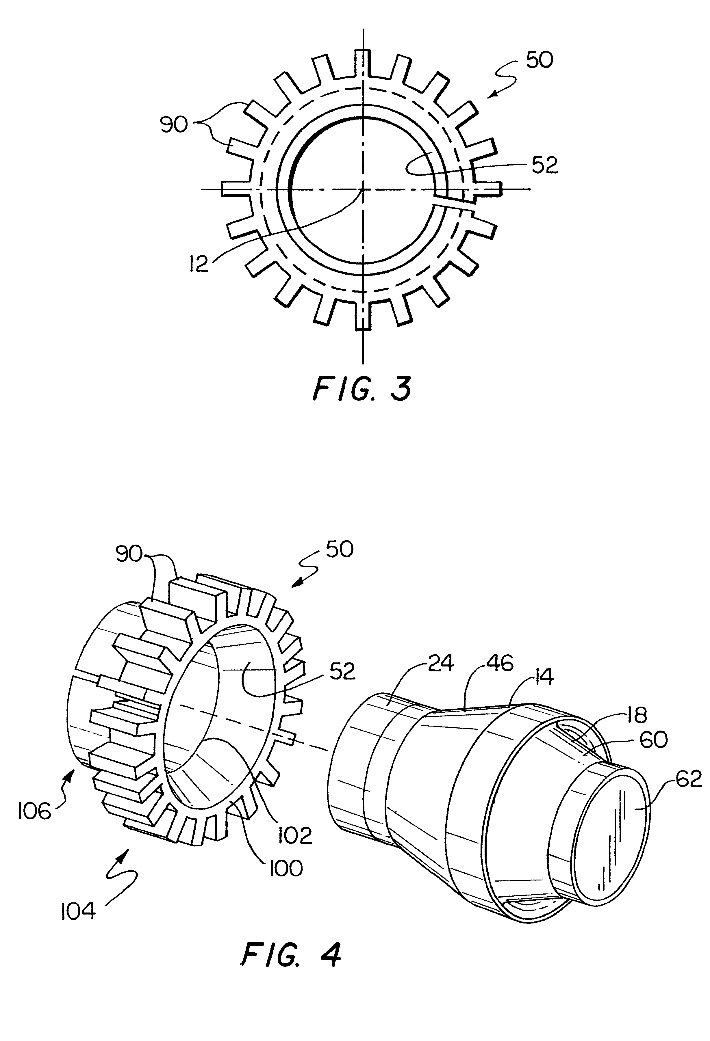
FIG. 3 is an end view of the heat sink of FIG. 1; and

FIG. 4 is a schematic assembly view of the gas discharge lamp of this invention.

There is shown in FIGS. 1, 2 and 3 a high power short arc gas discharge lamp 10, FIG. 1, in accordance with one embodiment of this invention. Lamp 10 is symmetrically circular about center line 12, FIG. 1. Lamp 10 includes a reflector body 14 made of a ceramic such as high alumina which is a good electrical insulator but a poor thermal conductor. Lamp 10 includes an anode assembly 16 at one end of reflector body 14 and a cathode assembly 18 at the other end...


PUM


Abstract

A high power short arc gas discharge lamp includes an electrically insulating reflector body having a concave internal reflector surface with a focal point; an anode and a cathode spaced from the anode to create an arc gap between them proximate the focal point; the reflector body having a conical external surface for reducing the thickness of the reflector body between the concave internal surface and the conical external surface; and an external electrically isolated heat sink mounted on the external conical surface proximate the arc gap.

Description

This invention relates to an improved high power short arc gas discharge lamp, and more particularly to such a lamp with improved heat dissipation.BACKGROUND OF INVENTIONConventional short arc lamps, using xenon, argon or other gases, produce a broad spectrum light of 200 nm to 1100 nm or more at 1 to 2 Kw using a curved, concave reflector such as a parabolic or elliptical shape surrounding the arc Substantial heat is generated by these devices and can cause rapid electrode erosion and even catastrophic failure. The reflective surface is typically a silvered coating on a ceramic body which electrically insulates the cathode assembly from the anode assembly and the reflective coating from both assemblies. The most intense heat is generated proximate the arc. The heat dissipation problem is exacerbated by the fact that neither the ceramic nor xenon or other gas are very good thermal conductors.In one approach the heat is removed using a large mass of highly thermally conductive materi...

Claims


Application Information

Patent Timeline
Patent Type & Authority Patents(United States)
IPC IPC(8): H01J61/30H01J61/52H01J61/02H01J61/86H01J61/84
CPCH01J61/025H01J61/86H01J61/523H01J61/30
Inventor MANNING, WILLIAM LAWRENCEVIDAL, DAVID PAUL
Owner EXCELITAS TECH
Why Eureka
Try Eureka