Polarization-sensitive corrugated quantum well infrared photodetector array

a well infrared photodetector and corrugated technology, applied in the direction of optical radiation measurement, radiation controlled devices, instruments, etc., can solve the problems of grating coupling or corrugation, optical elements in such systems have to be displaced or rotated, and detection camera systems are more expensive to implemen

Inactive Publication Date: 2002-06-25
ARMY US SEC THE
View PDF3 Cites 38 Cited by
  • Summary
  • Abstract
  • Description
  • Claims
  • Application Information

AI Technical Summary

Problems solved by technology

However, the use of grating coupling or corrugation coupling to detect polarization characteristics of incident infrared radiation is not suggested or taught by these teachings.
These earlier polarization detection systems taught by these studies have limitations that include: (1) The optical elements in such systems have to be displaced or rotated either manually or by automated mechanisms in a time-delayed manner since they are intended to observe an image wi...

Method used


Image

  • Polarization-sensitive corrugated quantum well infrared photodetector array
  • Polarization-sensitive corrugated quantum well infrared photodetector array
  • Polarization-sensitive corrugated quantum well infrared photodetector array

Examples


first array embodiment

FIG. 5 shows a two-dimensional n.times.m array having detector units (cells), each unit (cell) consist of detector elements A, B, C and D. The number of detector cells is arbitrary. The photocurrent generated in each detector element is connected to an electronic circuit for independent signal readout. The photocurrents J.sub.A, J.sub.B, J.sub.C, and J.sub.D from each detector unit (cell) are determined by the polarization properties of a particular spot in an observed scene. From the values of J.sub.A, J.sub.B, J.sub.C, and J.sub.D, the intensity components I.sub.u, I.sub.x and I.sub.y and the orientation angle .theta. can be calculated using Eqns. (21) and (20), respectively. In a sensitive camera, it is desirable that R.sub.xA >>R.sub.yA, and R.sub.xB <

R.sub.45C =R.sub.-45D, (22)

R.sub.-45C =R.sub.45D, (23)

and

R.sub.45C >R.sub.-45C...

second array embodiment

The second array embodiment of the invention is sensitive to both intensity and polarization characteristics of an observed scene.

In the first array 200A of the invention, there are four detector elements A, B, C and D in each detector unit 100A. With four detector elements, the state of polarization of light can be completely determined. On the other hand, for the purpose of object detection and recognition, there may not be need for complete information of the incident radiation upon the detector. For infrared detection, it is possible just to use two detectors in another form of a detector unit 100B for polarization-sensitive detection. With fewer detector elements in each unit, the resolution of a detector array can be doubled as shown in FIG. 9. The mathematical algorithm used can also be simplified.

In the following, we will use detectors A and B for illustration. Considering two objects, both emit radiation at the same intensity level. If the infrared detection is just based o...


PUM


Abstract

A polarization-sensitive infrared (IR) detector array for use in infrared cameras and other IR based instruments, is comprised of multiple corrugated quantum well infrared photodetector elements (C-QWIP) that form a unitary detector unit (cell). The array is preferably two-dimensional, which can detect polarization contrast of an observed object in a scene. Each detector unit (cell) is formed by a group of C-QWIP detector elements having different groove orientations and cross sections. Each detector unit (cell) has at least two C-QWIP detector elements with their respective corrugations orthogonally oriented. Infrared detection by these detector cells is primarily by polarization contrast, compared to intensity contrast, which is well known in the art. By measuring polarization of reflected light from the observed object, the type of material can also be identified. A first array embodiment of the invention comprises four C-QWIP elements that form a cell. The second array embodiment of the invention comprises a detector having two C-QWIPs to form a detector cell.

Description

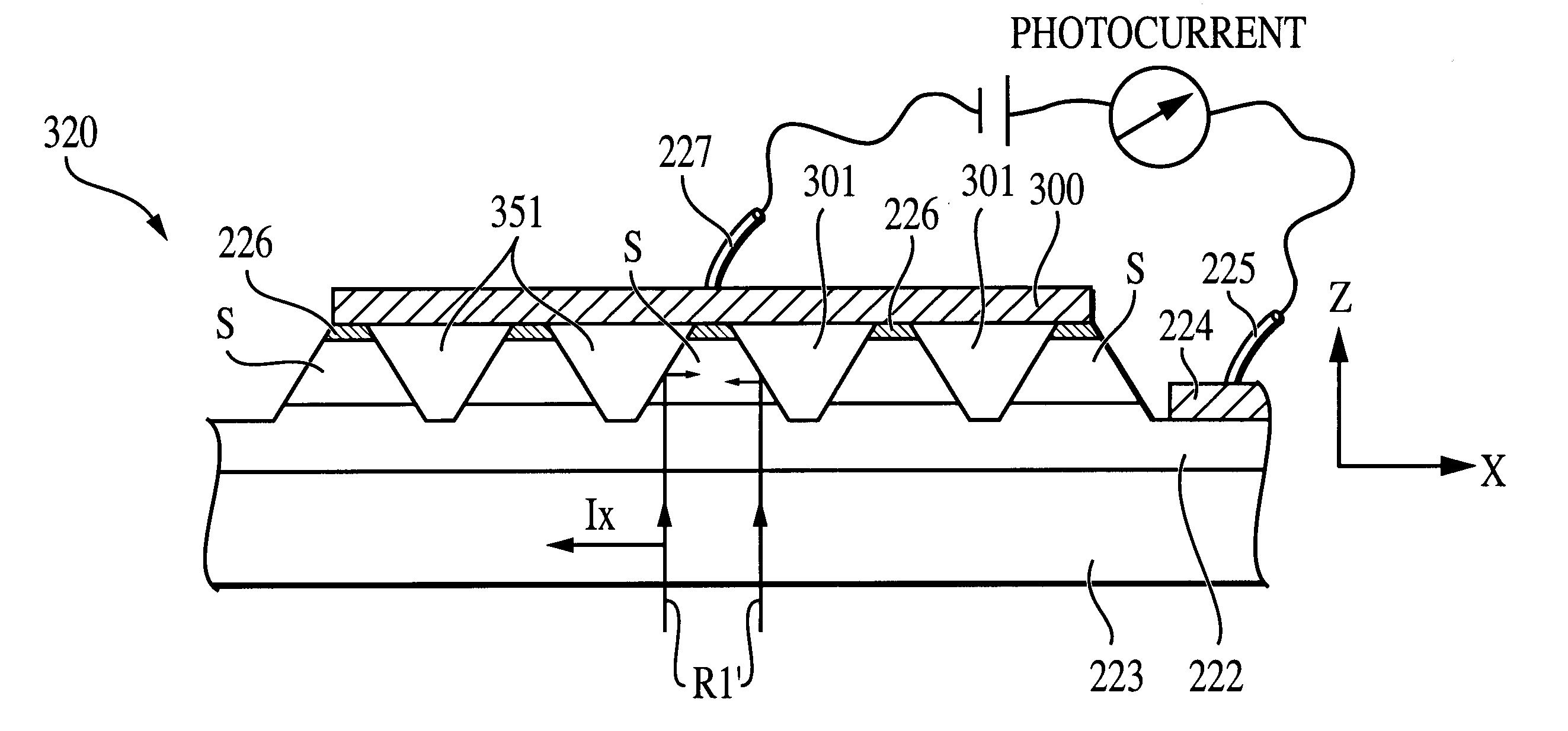
The invention relates in general to infrared image detection. More particularly, the invention relates to a polarization-sensitive infrared detection array using corrugated quantum well infrared photodetectors (C-QWIP) constructed to enable polarization-state detection of observed infrared radiation from a target object.DESCRIPTION OF THE PRIOR ARTA quantum well infrared photodetector (QWIP) is a superlattice semiconductor device that functions to produce intersubband transitions within a conduction band when a ground state electron is promoted to an excited state upon absorbing an incoming photon having energy equal to the subband spacing. Once in an excited state, the electron freely moves within the QWIP to form electrical current under bias. As such, QWIPs are often used to detect infrared (IR) radiation, QWIP arrays have been used to detect IR images.The physical construction of a conventional QWIP generally includes a stack of alternate semiconductor material layers sandwiched...

Claims


Application Information

Patent Timeline
IPC IPC(8): H01L27/146G01J5/20G01J4/00G01J4/04
CPCH01L27/1465H01L27/14601G01J4/04G01J5/20
Inventor CHOI, KWONG-KIT
Owner ARMY US SEC THE
Why Eureka
Try Eureka