Vehicle liftgate power operating system

a technology of operating system and liftgate, which is applied in the direction of roofs, doors, wing accessories, etc., can solve the problems of complicated power liftgate system, difficult to open and close, and difficult for people of shorter heights to close, so as to achieve convenient packaging, reduce the effect of weight and easy manufacturing and maintenan

Inactive Publication Date: 2002-07-30
STRATTEC POWER ACCESS
View PDF29 Cites 48 Cited by
  • Summary
  • Abstract
  • Description
  • Claims
  • Application Information

AI Technical Summary

Benefits of technology

Accordingly, among the objects of the present invention are to provide an improved vehicle liftgate power operating system that can be remotely controlled and electrically powered to move the associated liftgate from and between fully closed and fully open positions, usable in conjunction with a counterbalance system, electrically powered and capable of remote control, such as by the vehicle ECU unit, that is compact, rugged, requires a minimum of moving and stationary parts, economical to manufacture and maintain, easier to package than prior systems and provides better clearance with the vehicle head envelope than prior systems, lighter in weight, which is easily sealed against intrusion by car wash and rain water and against expulsion of lubricant contained in the liftgate power operating mechanism, which can be employed with single or dual output shaft electric motors, and that overcomes the aforementioned as well as other disadvantages of the prior art.
In one embodiment, an electric motor is directly mounted to the side of one of the housing half-shell parts and has a drive shaft that extends into the housing and is coupled in driving relation to a pinion gear disposed in constant mesh with the teeth of the curved rack. The rack subassembly is movably roller-supported within the housing by runner wheels attached to the rear ends of runner bars that track in the housing and by riding on a wheel mounted interiorly on the housing near its exit end. Dual hubs on the pinion gear overlie the smaller radius edges of the runner bars such that, in cooperation with the roller engagement of the runners within the housing, the rack is accurately maintained in any travel position during its bodily motion relative to the housing, the appropriate constant mesh tooth engagement is maintained between the pinion and rack during operation, and frictional resistance in the drive mechanism is substantially reduced. The pivotal mounting of the housing on the vehicle helps compensate for vehicle liftgate / body hinge mount assembly tolerance variations. The curvature of the housing and associated rack gear subassembly is uniform about a common center of curvature which in turn is coincident with the pivot axis of the liftgate-hinge. Thus insures a constant 1:1 ratio in the drive linkage action throughout operational travel of the rack gear subassembly in operating the liftgate between its fully closed and fully open positions.

Problems solved by technology

Some of these liftgates are large and heavy, thus making them difficult to open and close.
Some of the liftgates also reach a great distance above the ground when they are fully opened, thereby making them very difficult for people of shorter height to close.
This complicates power liftgate systems that rely on gas springs to assist in opening the liftgate.
If the total force exerted by the liftgate power closure varies substantially from one position between fully opened and closed to another position between fully opened and closed, it may be difficult for the control system to detect an obstruction and stop the liftgate without incurring damage to the vehicle or to the object that obstructs the liftgate.

Method used


Image

  • Vehicle liftgate power operating system
  • Vehicle liftgate power operating system
  • Vehicle liftgate power operating system

Examples


first embodiment

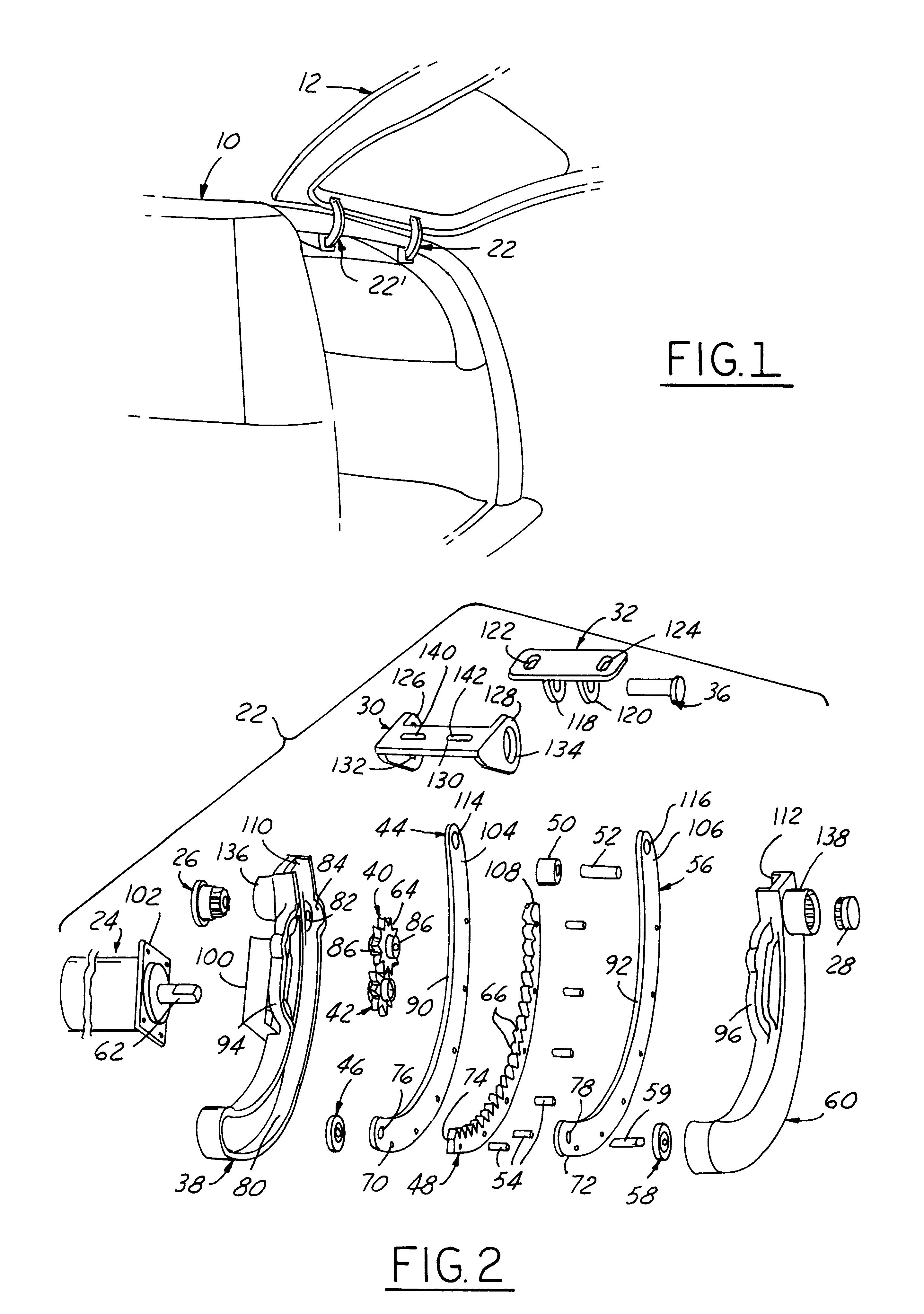
The first embodiment power operating system as described hereinabove preferably includes two identical drive units 22, 22' mounted as diagrammatically indicated in FIG. 1 for balanced operation and reduced manufacturing costs. However, the drive units need not be identical, and in some instances a single drive unit 22 may be sufficient. In addition, the two drive motors 24 may be eliminated and a single similar type motor gear reduction unit with a built-in clutch substituted that has a pair of drive shafts protruding one from each of the axially opposite ends of the motor casing. Such a unit may be interiorly centrally mounted to the aft rear body roof between such two motorless drive units 22 and 22', and then coupled to the spur gears 42 thereof by flexible drive shafts that are suitably encased in flexible covers that prevent contamination of the vehicle interior.

From the foregoing description, it will now be apparent to those of ordinary skill in the art, that the first embodim...

second embodiment

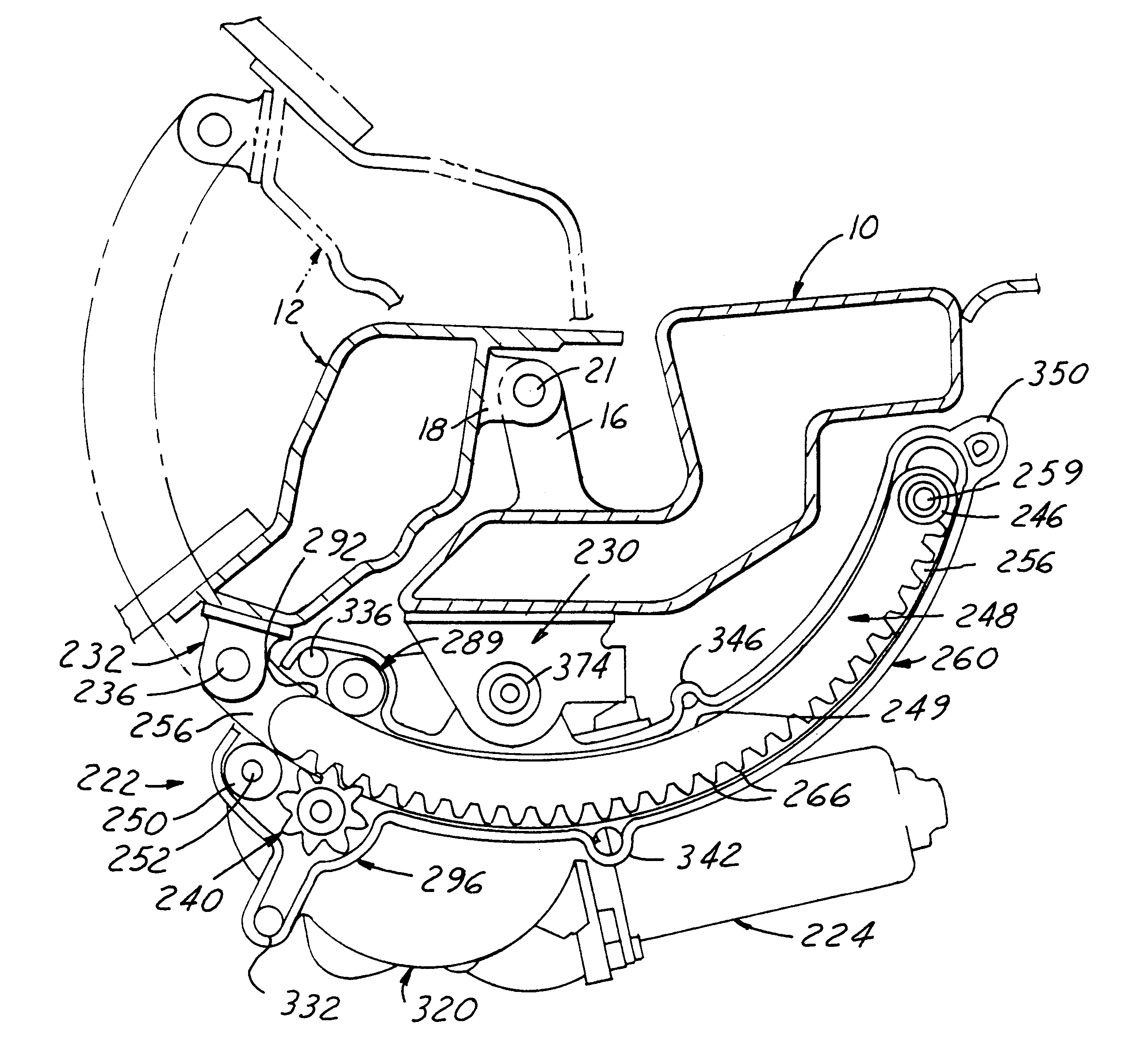
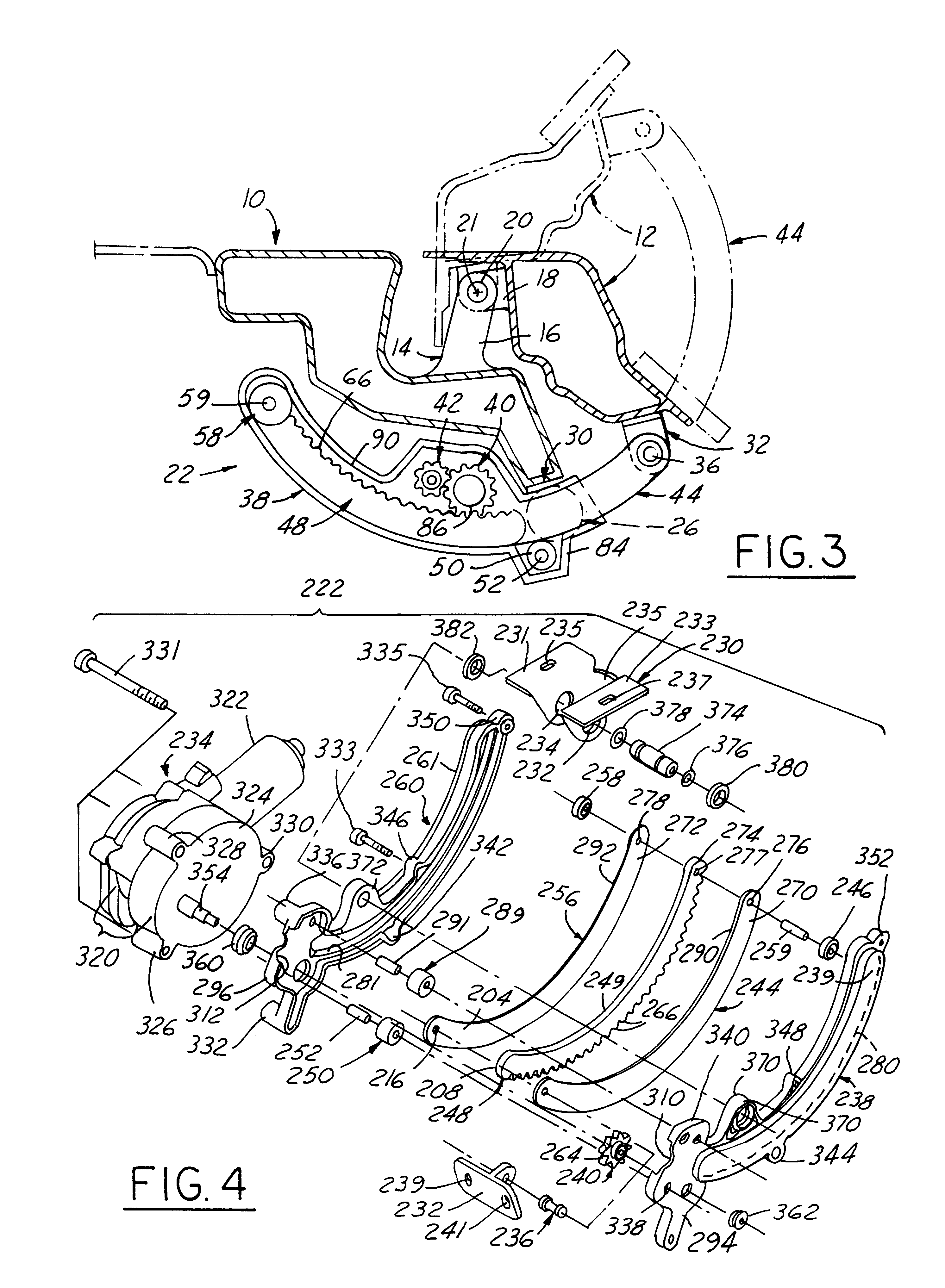
The second embodiment drive unit 222 is also modified with respect to the roller guided support of the rack / runner subassembly 244 / 248 / 256. The rear drive rollers for the rack / runner subassembly, namely rollers 246 and 258, are journaled by axle 259 inserted through the coaxially aligned mounting holes 276, and 278 of runners 244 and 256, and are also received through a coaxially aligned aperture 277 provided at the rear end of the rack segment 248. Rollers 246 and 258 rotatably run respectively on the track surfaces 280 and 281 of housing shells 238 and 260. Note that these roller guide tracks of the housing half-shell parts are formed as laterally outwardly protruding embossment portions 239 and 261, and thus are laterally offset clear of the motor mounting and bolt boss features of the housing. These latter mounting features of the housing are thus formed in a laterally offset peripheral boundary to the embossment portions 239 and 261 and have a larger width dimension than such e...


PUM


Abstract

A power operating system for opening and closing a vehicle liftgate has a pair of drive units supported on the vehicle roof and connected to the liftgate for opening and closing the liftgate. Each drive unit includes a housing having a curved track and a curved gear rack that is bodily movable endwise in the housing and guided by the curved track, the rack also serving as the drive link between the housing and the liftgate. The combined rack and drive link is extended and retracted by a pinion gear that is journalled interiorly in the housing and engages the teeth of the curved gear rack. The pinion gear is rotated by the output shaft of the motor, which in turn is fastened to the side of the housing. The motor is a reversible electric motor and is adapted to be operably coupled to the vehicle ECU unit and preferably includes an internal transmission and electrically operated clutch controlled by the ECU unit.

Description

This invention relates to a power operating system for a vehicle liftgate that is pivotally attached to a vehicle compartment for pivotal movement about a hinge axis that in normal orientation extends horizontally, and more particularly to a power operating system that will move such a liftgate from and between fully closed and fully open positions.Utility vehicles, vans and station wagons with rear liftgates that are hinged at the top about a generally horizontal axis are used by large numbers of people today. Some of these liftgates are large and heavy, thus making them difficult to open and close. Some of the liftgates also reach a great distance above the ground when they are fully opened, thereby making them very difficult for people of shorter height to close. For these and other reasons many people would like to have a power operating system for opening and closing the liftgate.A number of different liftgate openers have been tried in recent years. Some of these liftgate open...

Claims


Application Information

Patent Timeline
Patent Type & Authority Patents(United States)
IPC IPC(8): B60J5/10E05F15/12
CPCE05F15/619E05Y2201/246E05Y2201/462E05Y2900/546E05Y2201/216E05Y2201/722
Inventor WYGLE, MICHAEL GMARTIN, IANDOMBROWSKI, DOUGLASKUHLMAN, HOWARD WARREN
Owner STRATTEC POWER ACCESS
Why Eureka
Try Eureka