Bubbler tube with integral inlet pipe and bimetal core for injection molding tools and method of making the bubbler tube

a technology of injection molding tools and bubbler tubes, which is applied in the field of bubbler tubes with integral inlet pipes and bimetal cores for injection molding tools and the method of making bubbler tubes, can solve the problems of low cost, elongated cores, and the inability of cavity portions of molds to meet the needs of cooling fluid, and achieves high strength, high strength, and high strength.

Inactive Publication Date: 2002-07-30
CHECK JOHN M
View PDF7 Cites 21 Cited by
  • Summary
  • Abstract
  • Description
  • Claims
  • Application Information

AI Technical Summary

Benefits of technology

In accordance with this invention a mold assembly is provided that includes spaced, moveable mold parts, one mold part including a hollow cavity having a cavity inner surface configured to form an outer wall of an elongated, generally annular molded part and the other mold part including a corresponding core element having a core outer surface configured to form an inner wall of the molded part. The core element is at least partially disposed within the cavity and the core outer surface is spaced from the cavity inner surface defining a generally annular mold chamber for receiving molten material to be molded to the shape of the molded part. The core element has an open end and a closed end that defines an end portion of the core outer surface. The core element further includes a first portion of a high strength material defining a generally tubular core inner surface; a plurality of circumferentially spaced longitudinal ribs can be provided that extend radially inward from the core inner surface through part of the length of the core element. The ribs define a plurality of elongated coolant passages that receive return coolant flow from an annular space formed between a second reduced diameter hollow tip portion of the core element. A fluid inlet pipe is coaxially disposed within the core element. The fluid inlet pipe has a pipe outer surface spaced from the core inner surface, one end of the fluid inlet pipe connects to a source of coolant and a second end of the pipe is in fluid communication with the plurality of coolant passages. Such a construction is improved by providing a bimetal core element having a first portion formed of relatively high strength lower heat transfer material such as stainless steel and having a second portion defining a core element tip formed of a high strength alloy material to resist impact damage while providing increased thermal diffusivity and increased thermal conductivity. A fluid inlet pipe is assembled axially within the bimetal core element. Furthermore, the first and second portions can be connected by suitable bonding techniques so that the preexisting core elements of the types shown in copending United States Patent Applications can be upgraded.

Problems solved by technology

One problem with such arrangements is that molded parts having an elongated configuration must be formed, in part, by a core that has a length to width ratio large enough to allow the core to deflect when impacted by material that is injected against the core under high pressure conditions.
Since many materials are best shaped and densified under such high pressure conditions, one problem with prior art apparatus is how to provide a low cost, elongated core that will not deflect or warp under high temperature and high pressure operation.
Another problem with such molding apparatus is that the coolant flow is restricted to an annular surface in such a way as to limit the removal of heat from each of the mold cavities.
In addition, while the temperature of the core can be controlled using the fluid cooling system, the cavity portion of the mold cannot.
Copper core material, while having the ability to improve heat transfer from the core to the coolant fluid can be damaged by impacts thereon during the molding process.

Method used


Image

  • Bubbler tube with integral inlet pipe and bimetal core for injection molding tools and method of making the bubbler tube
  • Bubbler tube with integral inlet pipe and bimetal core for injection molding tools and method of making the bubbler tube

Examples


Embodiment Construction

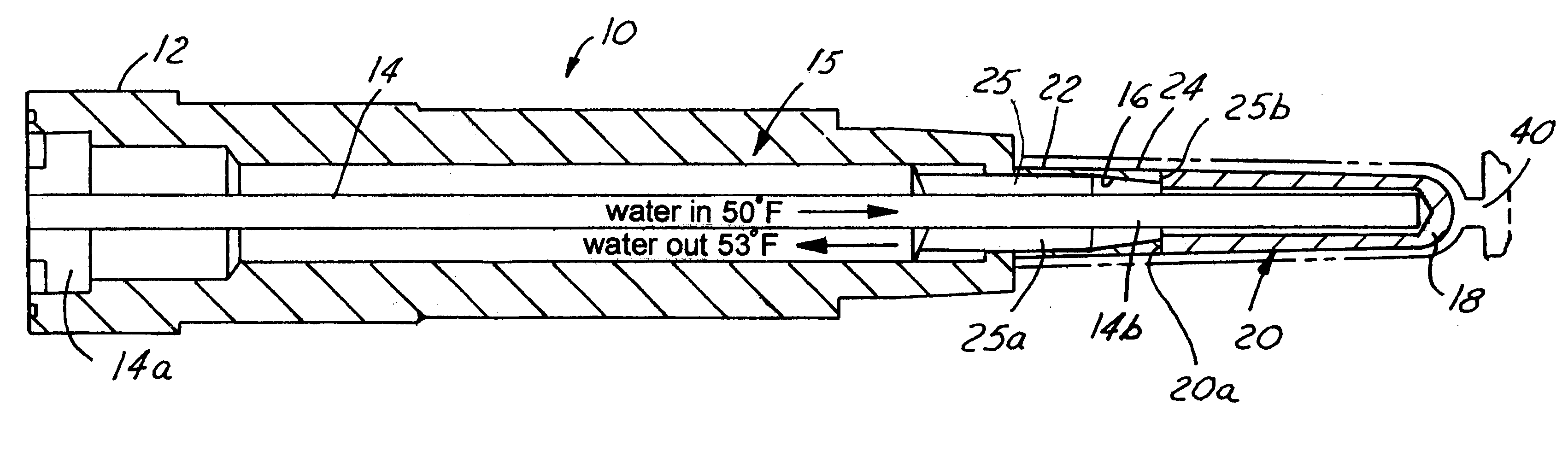
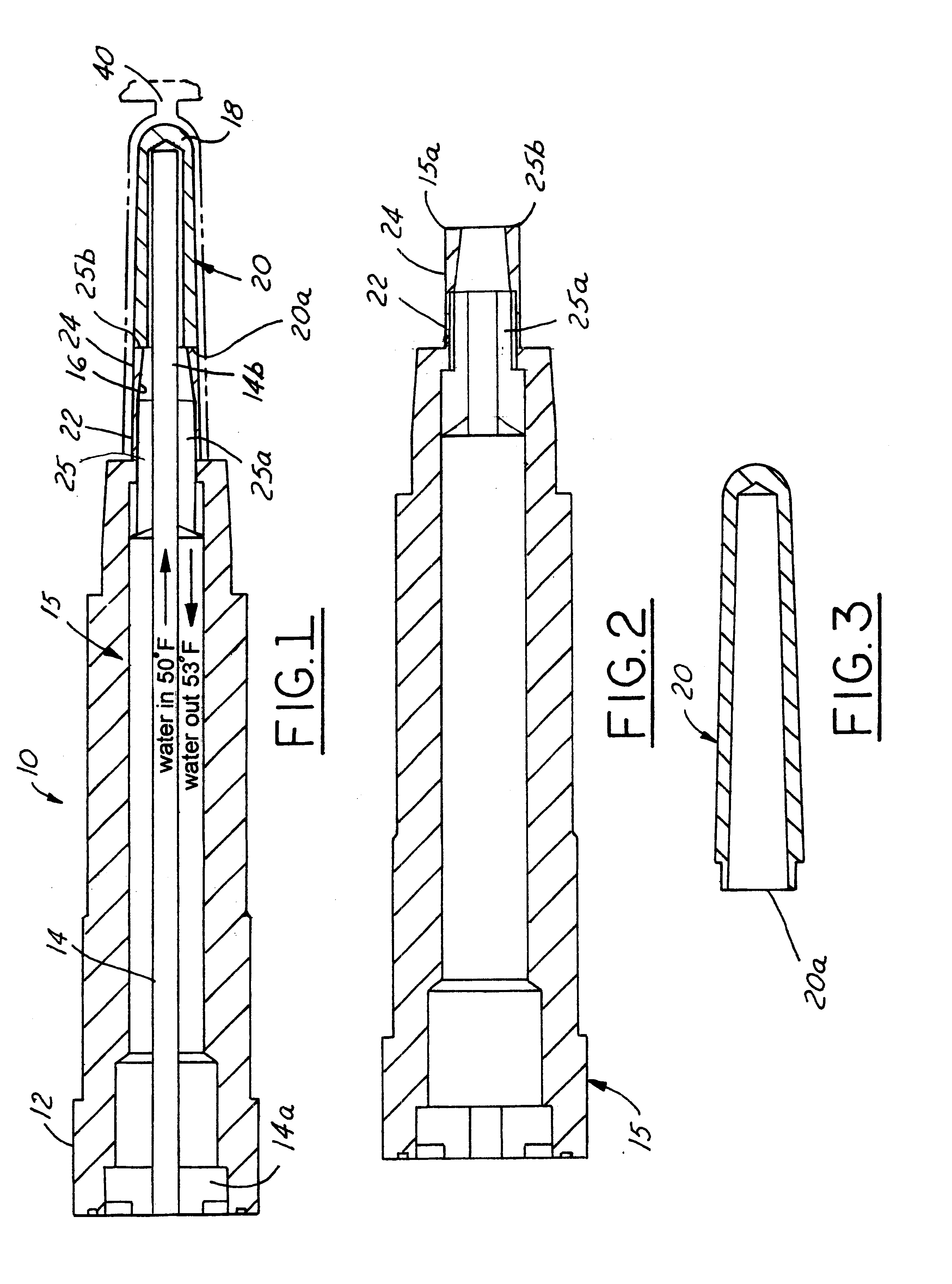
An integral bubbler type water-cooled core element or core assembly 10 is shown in FIG. 1 as having a core support portion 12, a bubbler tube 14 and a core 15. The bubbler tube 14 has an inlet segment 14a and an extension segment 14b. The core 15 has a cylindrical outer surface 16 and a closed end 18 of the type shown in the '150 patent. The core 15 further has a small diameter tip portion 20 and a large diameter portion 22 with a tapered portion 24 between the large and small diameter portions that in the present embodiment are thus configured for defining the inside surface of an injection molded member. that defines a hollow preform suitable for blowing molding a bottle or other blow molded article. The shape of the outer surface of the core 15 thus depends on the shape of the part to be injection molded about the core. In some cases the portions 20, 22 can be almost the same diameter with a small taper therebetween when, for example, the part being formed as a preform for hollow...


PUM

PropertyMeasurementUnit
strengthaaaaaaaaaa
thermal diffusivityaaaaaaaaaa
thermal conductivityaaaaaaaaaa

Abstract

A mold assembly including moveable mold parts, one of which includes a plurality of hollow cavities. Each hollow cavity forms an outer wall of an elongated, generally annular portion of a molded part and the other mold part includes a corresponding plurality of core elements, which form an inner wall of the same portion of the molded part. Each core is disposed within a corresponding cavity to define a generally annular mold chamber portion for receiving molten material to be molded to form the shape of the portion of the molded part. Each core element includes a cooling apparatus and each cavity includes an outside cavity-cooling device. Each core element includes a first portion made of high strength material and a tip portion made of material having a greater heat diffusivity and heat transfer coefficient than said first portion.

Description

This invention relates to molding apparatus and more particularly to molding apparatus having water-cooled core and cavity assemblies that cooperate to form hollow molded parts. The apparatus is an improvement on the molding apparatus shown in U.S. Pat. No. 5,498,150 issued to me on Mar. 12, 1996 and incorporated herein by reference.To decrease cycle time and to insure good molding of either metal casting or injection molded plastic parts, it is advantageous to provide coolant flow passages within a mold apparatus. When cooling fluid is passed through such passages during the molding process, it removes heat from the apparatus. Where a molding apparatus includes a mold cavity part that has a plurality of female cavities formed within it, and where those female cavities are configured to receive core parts that cooperate with the female cavities to form the surfaces of a molded part, apparatus for cooling has included a round cooling tube that is formed by the interior surface of the...

Claims


Application Information

Patent Timeline
Patent Type & Authority Patents(United States)
IPC IPC(8): B29C33/38B29C45/73B22C9/00B29C33/02
CPCB29C33/3828B29C45/73Y10T29/49728B29K2105/253
Inventor CHECK, JOHN M.
Owner CHECK JOHN M
Why Eureka
Try Eureka