
Process for continuous oxidation

a technology of oxidation and process, applied in chemical/physical/physical-chemical processes, chemical compound preparations, organic chemistry, etc., can solve the problems of pressure drop due to fittings such as perforated plates, pressure drop due to perforated plates, and uneconomical technical complexity

Inactive Publication Date: 2002-07-30
DEGUSSA AG
View PDF9 Cites 5 Cited by
  • Summary
  • Abstract
  • Description
  • Claims
  • Application Information

AI Technical Summary

Benefits of technology

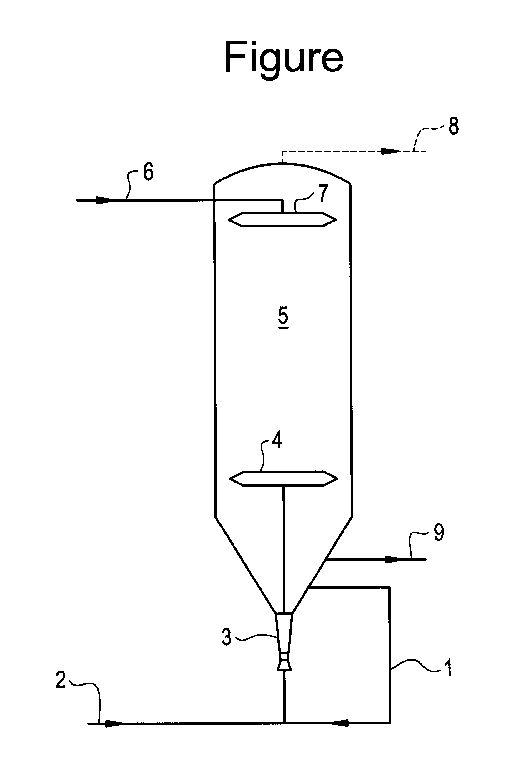
This result is surprising, since recycling a preoxidized split stream of product would normally reduce the space-time yield in the reactor. In fact the effect of mixing this split product stream with the oxidation gas before it enters the reactor, which is designed to be substantially free from coalescence-promoting fittings, is that the bubbles generated in the mixing organ retain their set size. This results in a reaction rate across the entire volume of the unencumbered reactor that is significantly higher than that achieved without premixing. This more than compensates for the loss in space-time yield arising from the recycling of a split product stream.
At the same time the countercurrent flow suppresses the formation of byproducts such as is known from a cocurrent flow. The premixing also increases the degree of oxidation. By bringing the split product stream into contact with fresh oxidation gas, further portions of unoxidized substance are reacted.

Problems solved by technology

In the anthraquinone process this oxidation was initially performed cocurrently in gas distribution towers connected in series using fresh air in each tower, which was both technically complicated and uneconomic.
Although the oxidation rate could be increased in a cocurrent flow of air and working solution according to U.S. Pat. No. 3,073,680 whilst retaining specific bubble sizes, obtainable by means of fine-pore gas distributor organs and specific cross-sectional loads, problems arose with the removal of the resulting foam and with the gas-liquid phase separation.
The disadvantage of this type of countercurrent flow is a very low flooding limit in the column, which means that several columns have to be connected in series in order to achieve as complete a conversion as possible.
The disadvantage of this cascade-type arrangement is the pressure drop due to fittings such as perforated plates, gauze or packing bodies, which are necessary for intimate and thorough mixing.
The disadvantage of this design proved to be that the reactor volume to be aerated (m.sup.3 per t H.sub.2 O.sub.2) is quite large, which leads to a lower space-time yield and to a high hold-up of expensive working solution.
This result is surprising, since recycling a preoxidized split stream of product would normally reduce the space-time yield in the reactor.
The premixing also increases the degree of oxidation.

Method used


Image

  • Process for continuous oxidation

Examples


Embodiment Construction

The process according to the invention can preferably be performed in such a way that the gas bubbles generated in the mixing organ have a maximum diameter of 2.5 mm, particularly preferably of less than 1.5 mm, in order to permit a rapid transfer to the liquid phase.

Examples of possible mixing organs with which this size of gas bubble can be achieved include perforated plates, diffuser stones, static mixers or nozzles.

A Venturi nozzle is particularly suitable for the process according to the invention. This known device has a lower pressure drop in comparison to other mixing organs. Depending on the energy supplied and the volumetric flow rate, the nominal width of the channel is set in such a way that the maximum gas bubble diameter does not exceed 2.5 mm.

The mixing organ is preferably positioned in such a way that the preoxidized substance can pass from the oxidation reactor to the mixing organ by natural circulation. The mixing organ can be fitted directly to the base or to the ...


PUM

PropertyMeasurementUnit
diameteraaaaaaaaaa
diameteraaaaaaaaaa
vol. %aaaaaaaaaa

Abstract

A continuous process for oxidation, in which the substance to be oxidized and the oxidizing gas flow countercurrently and the oxidizing gas is mixed with a split stream containing preoxidized substance before it enters the reactor. A Venturi nozzle is particularly suitable as the mixing organ in the reactor.

Description

INTRODUCTION AND BACKGROUNDThe present invention concerns a continuous process for oxidation. This process is particularly suitable for the oxidation step in the anthraquinone process for production of hydrogen peroxide, in which substituted anthrahydroquinones are oxidized by oxidation with an oxygen-containing gas to form substituted anthraquinones and hydrogen peroxide.In the anthraquinone process this oxidation was initially performed cocurrently in gas distribution towers connected in series using fresh air in each tower, which was both technically complicated and uneconomic. Although the oxidation rate could be increased in a cocurrent flow of air and working solution according to U.S. Pat. No. 3,073,680 whilst retaining specific bubble sizes, obtainable by means of fine-pore gas distributor organs and specific cross-sectional loads, problems arose with the removal of the resulting foam and with the gas-liquid phase separation.U.S. Pat. No. 2,902,347 describes the performance ...

Claims


Application Information

Patent Timeline
Patent Type & Authority Patents(United States)
IPC IPC(8): B01J4/04B01J19/24B01J4/00B01J19/26B01J10/00C01B15/023C01B15/00
CPCB01J4/04B01J10/002B01J19/2465B01J19/26C01B15/023B01J2219/00033B01J2219/00096B01J2219/185B01J2219/1943
Inventor MAURER, BERNHARD
Owner DEGUSSA AG
Learn More