Method of providing increased low-angle radiation sensitivity in an antenna and an antenna having increased low-angle radiation sensitivity

a radiation sensitivity and low-angle radiation technology, applied in the structure of radiating elements, substantially flat resonant elements, resonance antennas, etc., can solve the problems of increasing the demands of future telecommunication systems on antennas, presenting a number of difficulties for antennas, and not suitable for satellite communication services, etc., to improve radiation, improve low-angle radiation, and increase low-angle radiation

Inactive Publication Date: 2002-08-13
HRL LAB
View PDF20 Cites 42 Cited by
  • Summary
  • Abstract
  • Description
  • Claims
  • Application Information

AI Technical Summary

Benefits of technology

In one aspect the present invention provides a technique to produce an electrically thin antenna that has increased low-angle radiation in comparison with other antennas having a similar profile. It does this by using an area of a high-impedance surface which is encompassed by a larger region of metal surface. Producing improved low-angle radiation is accomplished through the excitation of a tangential electric field on the high-impedance surf

Problems solved by technology

This antenna presents a number of difficulties.
First, it is not suitable for use with satellite communication services including current GPS and direct satellite broadcast services since those services may rely on satellites positioned most or less overhead where the vertical antenna lacks sensitivity.
Second, future telecommunication systems will put more demands upon antennas.
Third, these vertical antennas are (i) unsightly, (ii) subject to increased risk of breakage and damage and (iii) non-aerodynamic, particularly as their numbers increase.
However this can involve radiating at a low angle across a large metal surface, which is difficult particularly for horizontal or circular polarizations.
The use of a tall vertical antenna reduces the aerodynamic performance of the vehicle and is often quite undesirable for aesthetic styling purposes.
At the same time, vehicle styling and/or aerodynamic requirements prohibit the use of unsightly "antenna farms or forests" with multiple vertical antennas protruding from the surface of a vehicle.
In many situations, these two requirements are in direct conflict.
For vehicle antennas, which are typically mounted on the top of the roof in order to obtain unobstructed coverage of all azimuthal angles, the presence of a large metal ground plane complicates the situation.
However, as mor

Method used


Image

  • Method of providing increased low-angle radiation sensitivity in an antenna and an antenna having increased low-angle radiation sensitivity
  • Method of providing increased low-angle radiation sensitivity in an antenna and an antenna having increased low-angle radiation sensitivity
  • Method of providing increased low-angle radiation sensitivity in an antenna and an antenna having increased low-angle radiation sensitivity

Examples


Embodiment Construction

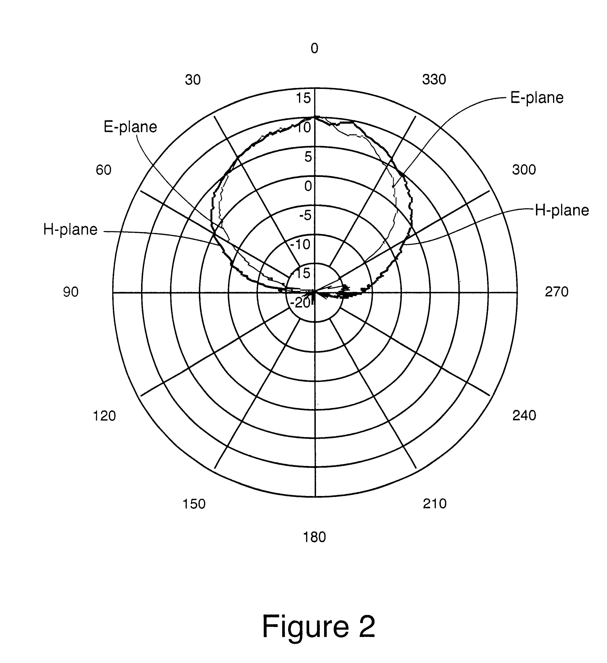
In some situations, it is desirable to enhance surface currents, or to excite them to a greater degree than would be possible with an ordinary antenna. It has been found experimentally that this can also be done using a conventional Hi-Z surface, by operating it in a frequency range in which it is not normally used, that is, in a leaky TE wave range. Results of experiments which were performed are shown in FIGS. 4a-4c. As can be seen by reference to FIG. 4c, the H-plane radiation pattern is similar to that of the patch antenna, but the E-plane radiation pattern shows greatly enhanced radiation near the horizon. The E-plane is the plane that is perpendicular to the surface, and which contains the wire. The H-plane is perpendicular to both the surface and the wire.

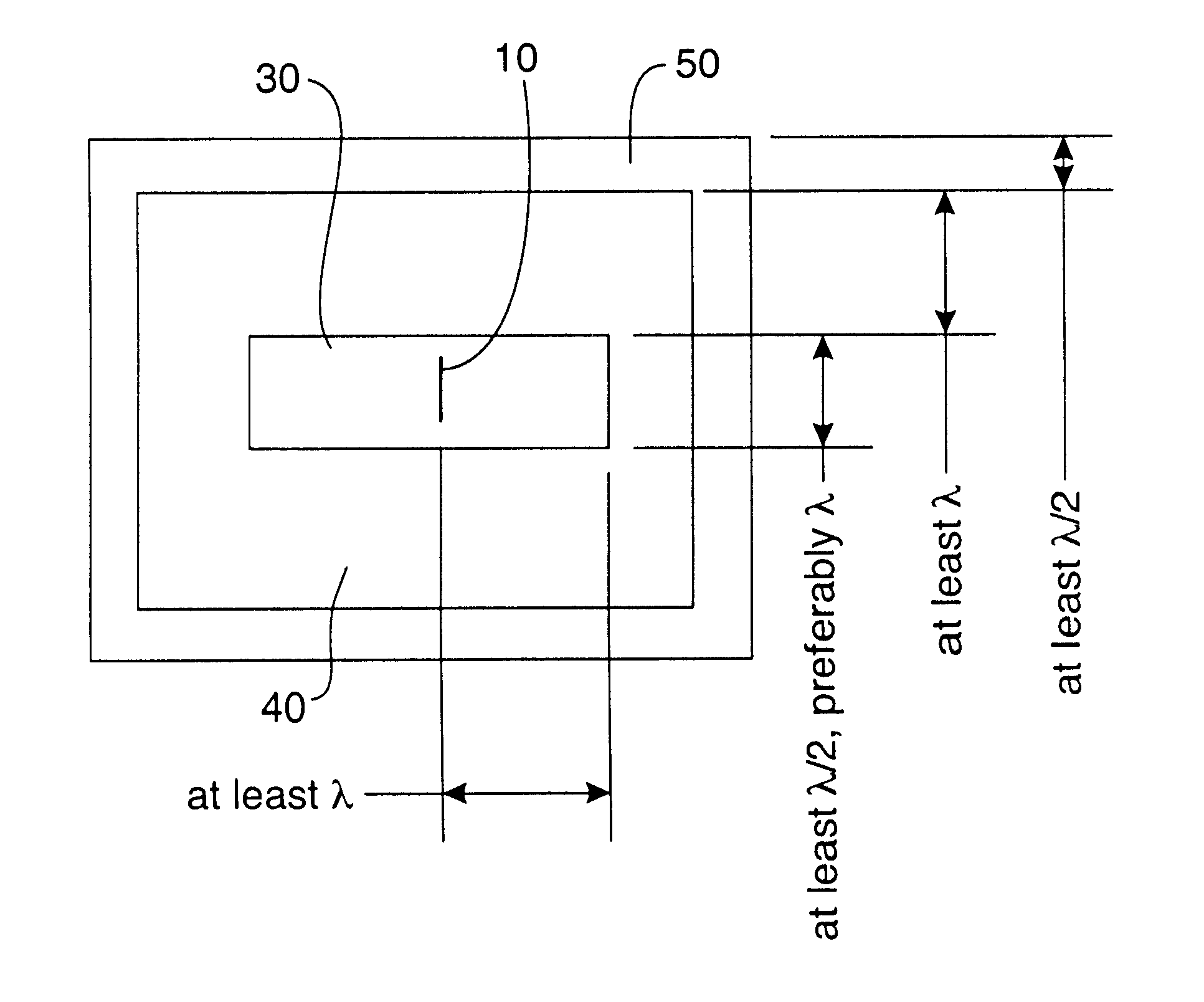
One experiment was performed as follows: The antenna under test consisted of a thin wire that was about 4 cm long. It was centered in a 12 cm by 12 cm Hi-Z surface 30 which was centered on a 60 cm by 60 cm metal ground plane...


PUM


Abstract

An improved low-angle radiation antenna is obtained through excitation of a tangential electric field on the high-impedance surface, as well as leaky transverse-electric surface waves. Such fields and surface waves cannot normally occur on an ordinary metal surface. The tangential electric field on the high-impedance region excites a transverse-magnetic surface wave on a surrounding metal surface which gives improved low-angle radiation in the E-plane of an antenna disposed on the high impedance surface. Leaky transverse-electric surface waves provide improved radiation in the H-plane of the antenna.

Description

This invention relates to thin or low-profile antennas, and particularly to thin or low-profile antennas having good radiation capacities for receiving and / or sending radio frequency signals at a low angle to the major surface of the antenna.BACKGROUND AND FEATURES OF THE INVENTION AND CROSS REFERENCE TO RELATED APPLICATIONSThe standard telecommunications (e.g. cellular telephone) antenna seen on the exteriors of automobiles today is a vertical antenna. This antenna presents a number of difficulties. First, it is not suitable for use with satellite communication services including current GPS and direct satellite broadcast services since those services may rely on satellites positioned most or less overhead where the vertical antenna lacks sensitivity. Second, future telecommunication systems will put more demands upon antennas. If vertical antennas were used to try to meet this demand, a number of antennas would be installed on the roof of a vehicle and as the desired performance o...

Claims


Application Information

Patent Timeline
IPC IPC(8): H01Q13/10H01Q15/00H01Q9/04H01Q1/38
CPCH01Q1/38H01Q9/0407H01Q13/10H01Q15/008
Inventor SIEVENPIPER, DANIEL F.SCHAFFNER, JAMES H.HSU, HUI-PINTANGONAN, GREGORY L.
Owner HRL LAB
Why Eureka
Try Eureka