Cooling air arrangement for a heat exchanger of an aircraft air conditioning unit

a technology for cooling air and aircraft air conditioner, which is applied in the direction of domestic cooling apparatus, lighting and heating apparatus, and cooling fluid circulation, etc. it can solve the problems of insufficient or non-existent ram air flow, inability or suffering considerable aerodynamic disadvantages, and large design complexity of turbo blower or fan 3', etc., to achieve efficient air flow, low flow energy loss, and compact arrangement

Inactive Publication Date: 2002-08-20
AIRBUS OPERATIONS GMBH
View PDF8 Cites 34 Cited by
  • Summary
  • Abstract
  • Description
  • Claims
  • Application Information

AI Technical Summary

Benefits of technology

In view of the above, it is an object of the invention to provide a cooling air arrangement for a heat exchanger of an aircraft air conditioning unit with an integrated turbo blower or fan, which achieves a very compact arrangement with an efficient air flow and low flow energy losses, especially for an orientation and arrangement of the components in which the air inlets and air outlet directions face generally in the same direction, and particularly the flight direction of the aircraft. The invention further aims to avoid or overcome the disadvantages of the prior art, and to achieve additional advantages, as apparent from the present specification.

Problems solved by technology

On the other hand, in a second air flow condition, when the aircraft is parked or taxiing on the ground or in low speed or low altitude flight, whereby nonetheless the air conditioning unit is to be operated to provide air conditioning air, there is insufficient or non-existent ram air flow to provide the required flow rate of cooling air, so it is necessary to mechanically drive an air flow through the heat exchanger using a turbo air machine such as a fan or blower.
The mechanical, structural, aerodynamic, and air flow arrangement and configuration of the several components and particularly the outlet plenum 4', the first channel 7', the second channel 9', and the turbo blower or fan 3' are very significant and rather complicated to design.
Any attempt to achieve such a configuration or orientation using the cooling air arrangements according to conventional FIGS. 4 and 5 would be impossible or suffer considerable aerodynamic disadvantages, or would simply not be able to achieve acceptable operating characteristics.
This would lead to a disadvantageous increase of the installation size and weight of the overall arrangement, as well as requiring additional maintenance efforts.
Also, the aerodynamic efficiency of the cooling air channel directing air through the heat exchanger would be reduced due to the extra air channel components and deflections, and heat exchange energy would thereby be lost.
It would also be necessary to increase the size of the various air channel components to try to compensate for such a loss of aerodynamic efficiency, which in turn would result in a greater installation space requirement as well as an increased total weight in the aircraft.

Method used


Image

  • Cooling air arrangement for a heat exchanger of an aircraft air conditioning unit
  • Cooling air arrangement for a heat exchanger of an aircraft air conditioning unit
  • Cooling air arrangement for a heat exchanger of an aircraft air conditioning unit

Examples


Embodiment Construction

The conventional arrangements according to FIGS. 4 and 5 will not be described further here, because they have been adequately discussed in the above Background Information section of this specification. Moreover, a person of ordinary skill in the art will be familiar with and have additional information available regarding these prior art configurations as shown in FIGS. 4 and 5.

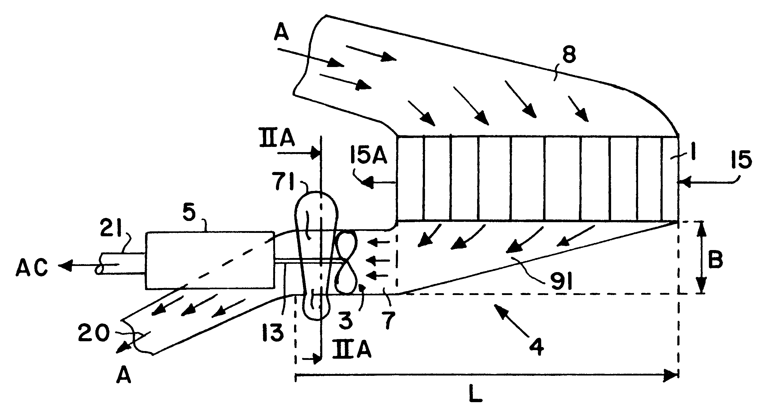
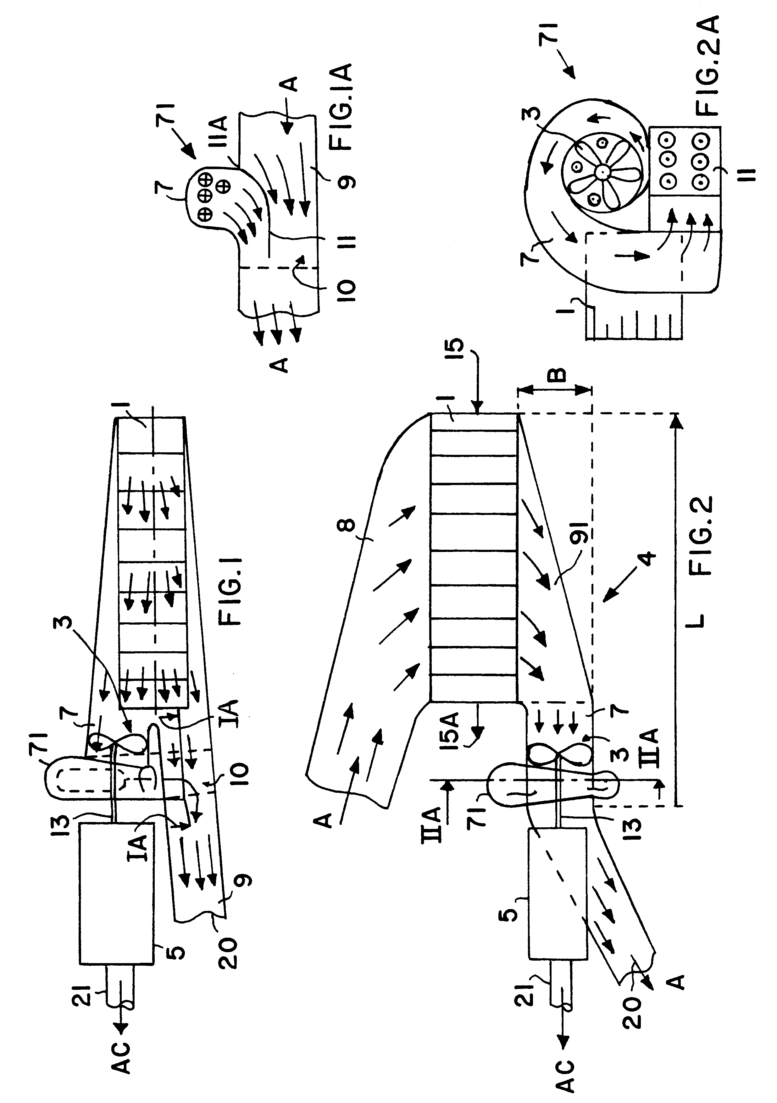
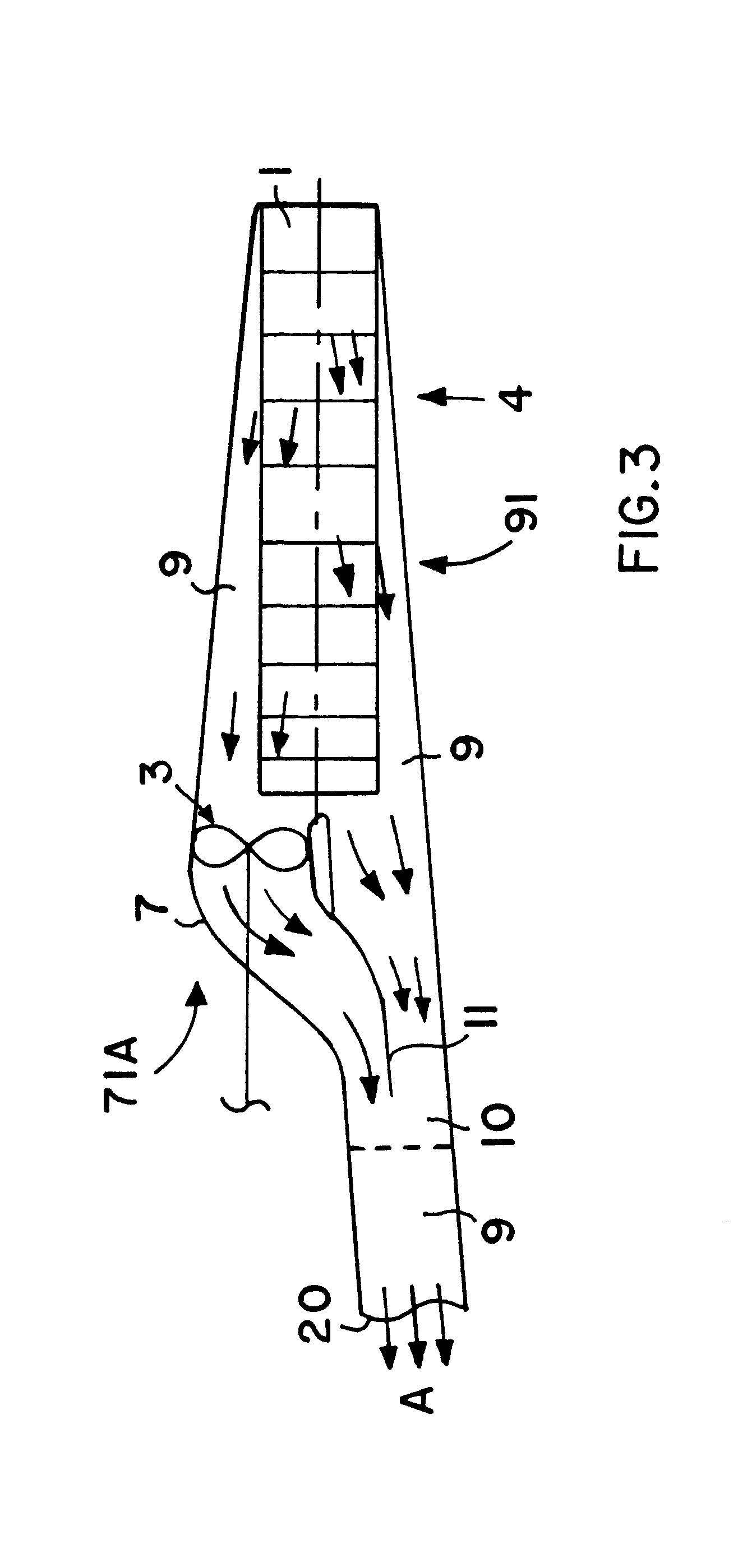
FIG. 1 shows a schematic side view of a first example embodiment of a cooling air arrangement for a heat exchanger of an aircraft air conditioning unit according to the invention. FIG. 2 shows a schematic top view of the same arrangement. The arrangement primarily comprises a cooling air inlet channel 8, a heat exchanger 1 primarily including a heat exchanger core, and an air outlet channel system including a heat exchanger plenum or cooling air outlet plenum 4, and a two-part divided outlet air channel including a first outlet channel 7 and a second outlet channel 9. An air-sucking turbo blower or fan 3 is...


PUM


Abstract

A cooling air arrangement for an aircraft air conditioning unit includes an air inlet, a heat exchanger, an outlet plenum, first and second air outlet channels branching from the plenum, and a fan arranged in the first outlet channel. During flight of the aircraft, external ram air driven into the air inlet flows primarily through the second outlet channel. During ground operation, the fan primarily sucks cooling air through the first outlet channel, which merges back into the second outlet channel at an air mixing junction that functions as an injector nozzle and a non-return flap valve. The first outlet channel is provided in a spiral housing of the fan, or in a smooth curved duct. The air inlet and outlet of the cooling air arrangement, and the air outlet of the air cycle machine, are oriented in the same direction, e.g. the flight forward direction.

Description

PRIORITY CLAIMThis application is based on and claims the priority under 35 U.S.C. .sctn.119 of German Patent Application 100 15 570.7, filed on Mar. 29, 2000, the entire disclosure of which is incorporated herein by reference.FIELD OF THE INVENTIONThe invention relates to an arrangement for directing both ram air as well as fan-driven air through a heat exchanger that is used for cooling hot compressed air for an air conditioning unit of a passenger transport aircraft.BACKGROUND INFORMATIONModern passenger transport aircraft are typically equipped with air conditioning units, namely so-called air conditioning packs or air generation units. Hot, highly compressed engine bleed air is conveyed to the air conditioning units through suitable conduits or ducts, and in the air conditioning units is then subjected to a combined thermodynamic process generally including cooling by heat transfer through a heat exchanger, followed by compression, further intermediate cooling in a heat exchang...

Claims


Application Information

Patent Timeline
Patent Type & Authority Patents(United States)
IPC IPC(8): B64D13/08B64D13/00
CPCB64D13/00B64D13/08
Inventor BUCHHOLZ, UWE ALBERTKELNHOFER, JUERGEN
Owner AIRBUS OPERATIONS GMBH
Why Eureka
Try Eureka