Exhaust gas turbocharger turbine

a turbocharger and exhaust gas technology, applied in the direction of machines/engines, reaction engines, liquid fuel engines, etc., can solve the problems of full-load operation efficiency loss and consumption disadvantages, and achieve the effect of reducing the thermal loading of engine components, and braking the piston

Inactive Publication Date: 2002-09-03
DAIMLER AG
View PDF16 Cites 42 Cited by
  • Summary
  • Abstract
  • Description
  • Claims
  • Application Information

AI Technical Summary

Benefits of technology

In an inventive manner, with the guide cascade, the supercharging potential of the exhaust-gas turbocharger is now also utilized during the engine braking operation. To this end, during braking operation, the guide cascade is pushed with an appropriate axial displacement of the support into the flow gap, in which case the guide blades can be arranged radially so as to be optimized in terms of flow in such a way hat the exhaust-gas turbine continues to run even at a low residual-gas flow. On the one hand, this supercharges the engine, whereby the gas flow on the exhaust-gas side is then consequently increased in turn, and on the other hand the exhaust-gas back pressure is thus also increased, which at the same time allows the turbine to rotate even faster.
This process is repeated until the exhaust-gas back pressure is so great that the engine speed no longer increases. The braking action of the engine and thus that of the vehicle takes place because the additional air and the additional exhaust-gas back pressure in the combustion space have a very powerful braking effect on the piston and, at the end of the compression phase, the compressed air is discharged into the exhaust system in a known manner via a valve additionally located in the cylinder head, e.g. a constant choke. In this way, the energy in the form of compressed air is not returned again to the piston.
With the solution according to the invention, a higher braking performance with simultaneous reduction in the thermal loading of engine components, in particular of injection nozzles, is achieved. At the same time, an improvement in the dynamic driving behaviour of the vehicle is thereby achieved, since the turbocharger continues to run during the braking of the engine and a charge pressure is immediately present again at the engine during a subsequent acceleration action. In this way, a so-called turbohole is avoided.

Problems solved by technology

A disadvantage in this case, however, is the fact that, although better acceleration is achieved within the part-load range by the flow guide device having the guide blades, efficiency losses and consumption disadvantages occur in full-load operation.

Method used


Image

  • Exhaust gas turbocharger turbine
  • Exhaust gas turbocharger turbine
  • Exhaust gas turbocharger turbine

Examples


Embodiment Construction

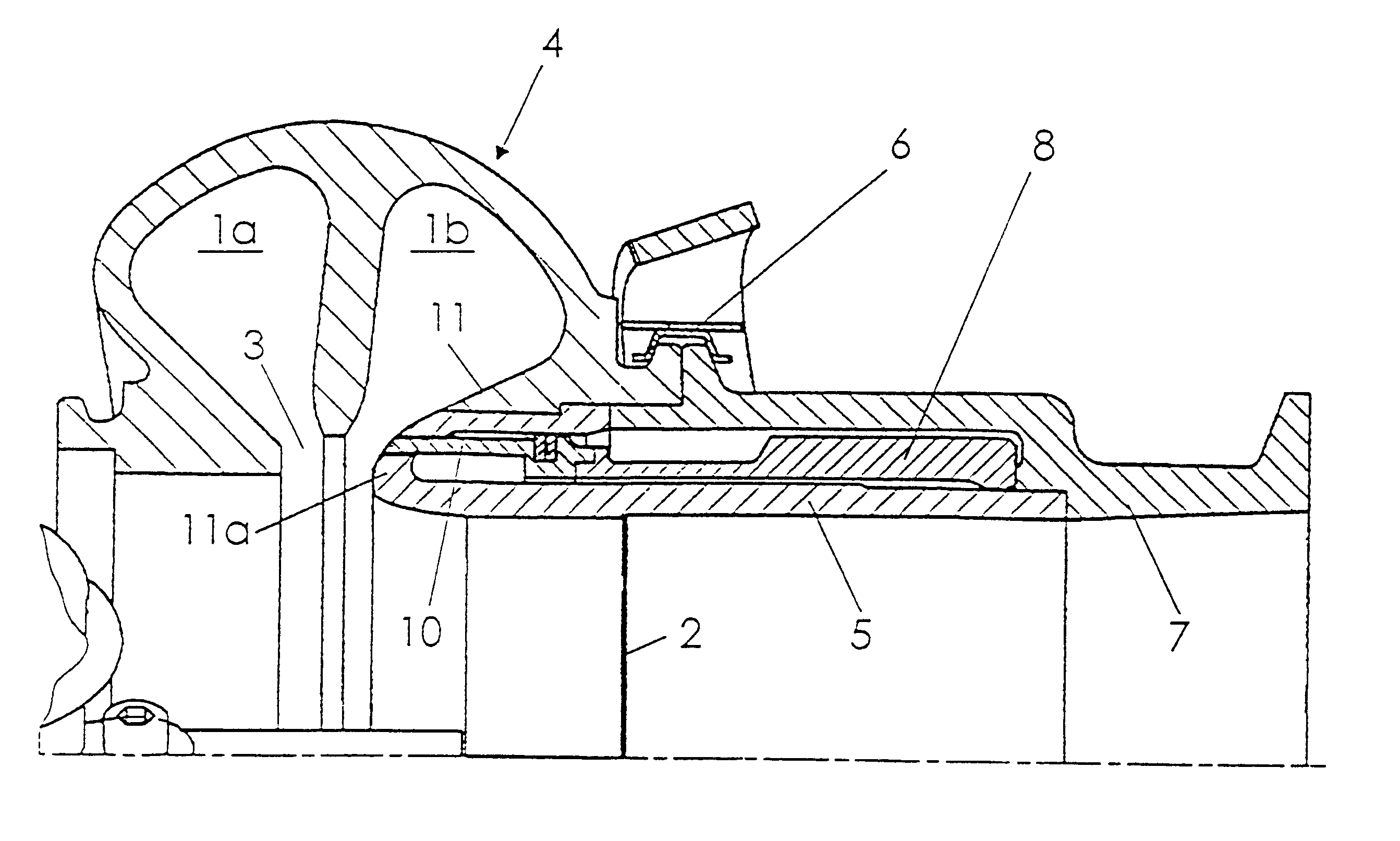
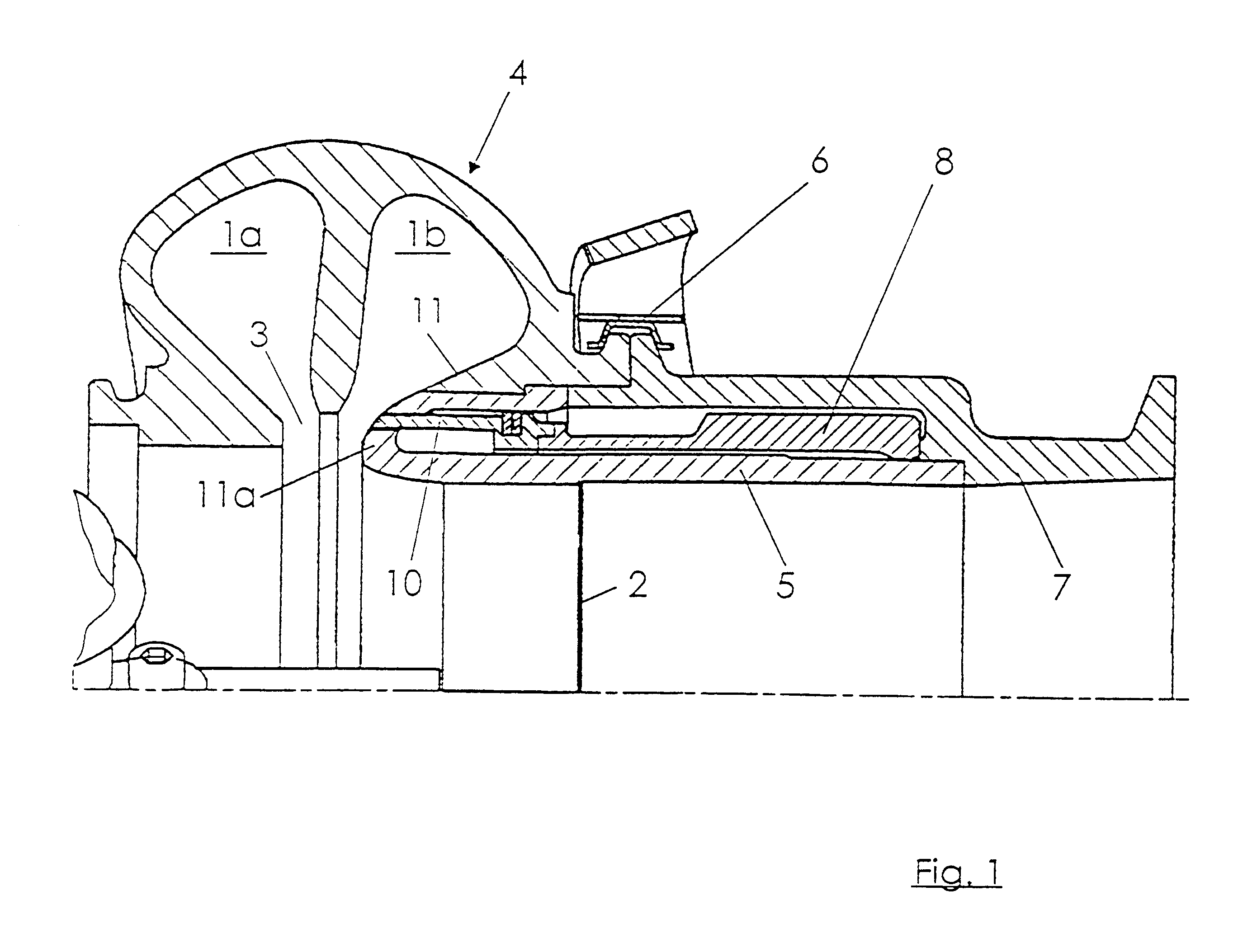
An exhaust-gas turbocharger turbine of known type of construction having a double-flow spiral guide passage 1a and 1b, a turbine impeller 2, and a flow gap 3 between the guide passages 1a and 1b and the turbine impeller 2 is shown in the exemplary embodiment. An inner sleeve 5 which forms a flow guide for the exhaust gases leaving the turbine impeller 2 is located in the turbine housing 4. An exhaust-gas flange 7 is connected to the turbine housing 4 via a tightening strap 6.

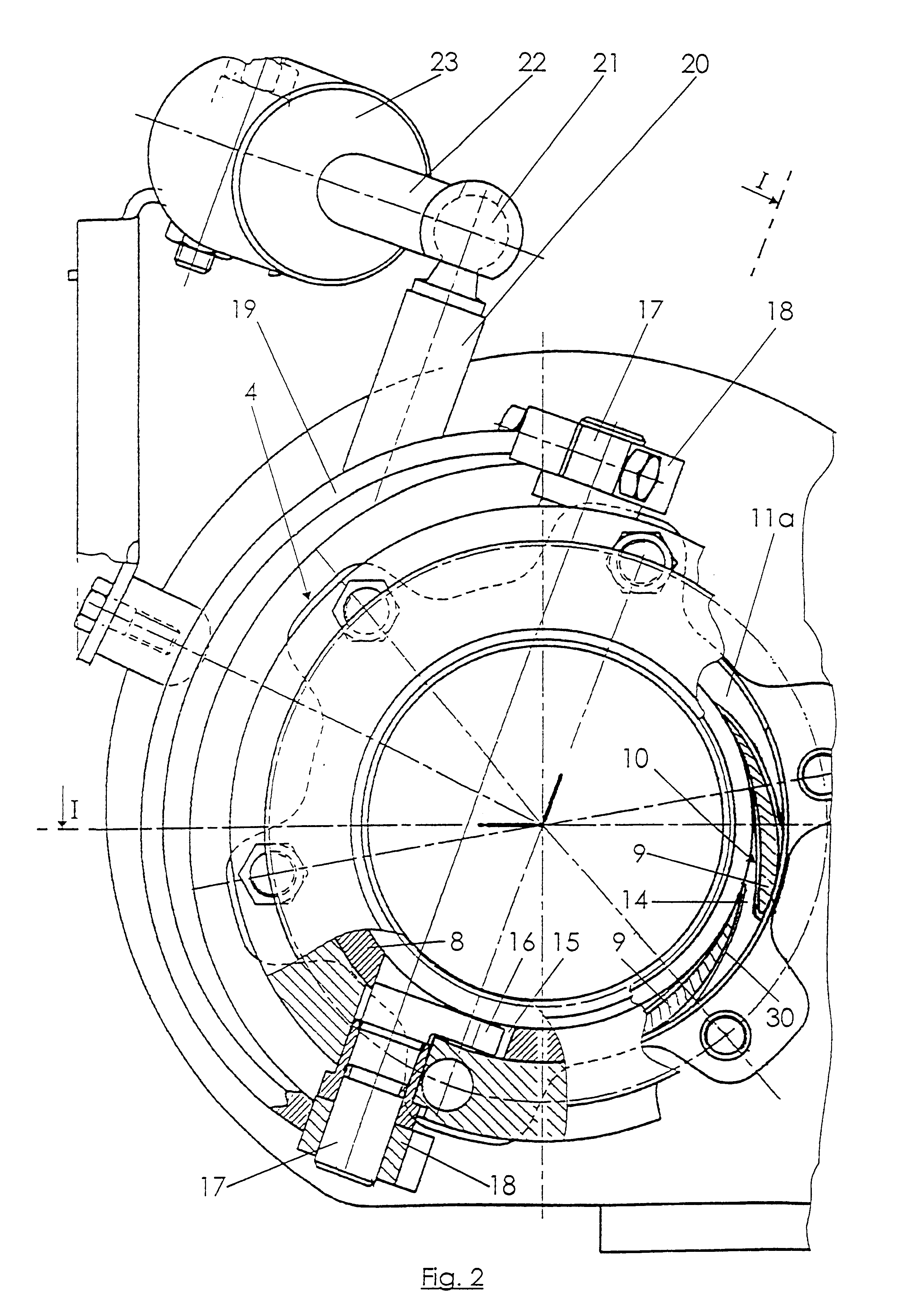
Axially outside the flow gap 3, a support in the form of a sleeve 8 is arranged on the outer circumference of the inner sleeve 5 so as to be axially displaceable coaxially to the longitudinal axis of the turbine impeller 2. Projecting from that end face of the sleeve 8 which faces the flow gap 3 are guide blades 9, which form a guide cascade 10, for which purpose the guide blade 9 are arranged so as to be appropriately distributed in a ring shape over the circumference. In the pushed-back or pushed-in state of t...


PUM


Abstract

An exhaust-gas turbocharger turbine of an internal combustion engine is provided with a spiral guide passage arranged in a turbine housing, a turbine impeller, a flow gap be ween the guide passage and the turbine impeller, and guide blades forming a guide cascade. The guide cascade with the guide blades projects axially from a support, arranged so as to be displaceable in the axial direction in the turbine housing, in such a way that the guide blades, in normal operation, are mounted in recesses of a housing wall part of the turbine housing, the recesses, in the form of a female piece, forming a mating profile shape for the guide blades. In braking operation of the internal combustion engine, the guide blades project into the flow gap during an axial displacement of the support. The device with actuation for the braking operation can be fitted as a complete module into the turbine spiral.

Description

The invention relates to an exhaust-gas turbocharger turbine.An exhaust-gas turbocharger turbine of the generic type is described in DE 42 32 400 C1. In this case, an adjustable flow guide device having guide blades for controlling the exhaust-gas passage in normal operation, in particular within the part-load range of the internal combustion engine, is located in the flow gap between the guide passage and the turbine impeller. In addition, the adjustable flow guide device, which is located continuously in the flow gap, is also used for a braking operation of the internal combustion engine.A disadvantage in this case, however, is the fact that, although better acceleration is achieved within the part-load range by the flow guide device having the guide blades, efficiency losses and consumption disadvantages occur in full-load operation.Similar adjustable low guide devices for exhaust-gas turbines of exhaust-gas turbochargers are described in DE 43 03 520 C1 and 43 03 521 C1.With reg...

Claims


Application Information

Patent Timeline
Patent Type & Authority Patents(United States)
IPC IPC(8): F01D17/14F01D17/16F01D17/00F02D9/06F02B37/22F02B37/12F02D9/00F02C6/00F02C6/12F02B39/00F02B37/24
CPCF01D17/143F01D17/165F02C6/12F02D9/06F02B37/025F02B37/22
Inventor ERDMANN, WOLFGANGFUNKE, CARSTENHARDT, THOMASLOFFLER, PAULSCHMIDT, ERWINSUMSER, SIEGFRIED
Owner DAIMLER AG
Why Eureka
Try Eureka