Geometric distortion correction in magnetic resonance imaging

a magnetic resonance imaging and distortion correction technology, applied in the field of geometric distortion correction in magnetic resonance imaging, can solve the problems of limited ability to differentiate between components of inhomogeneous soft tissue structures, the frequency of use of ct is limited, and the usefulness of ct in imaging bony structures

Inactive Publication Date: 2002-09-03
CASE WESTERN RESERVE UNIV
View PDF3 Cites 94 Cited by
  • Summary
  • Abstract
  • Description
  • Claims
  • Application Information

AI Technical Summary

Benefits of technology

FIG. 2B illustrates bow tie effect distortion in an MR image;
FI

Problems solved by technology

CT is useful in imaging bony structures yet has limited ability to differentiate between components of inhomogeneous soft tissue structures, such as the brain for example.
As CT also involves X-ray exposure, its frequency of use must be limited to avoid tissue burning and genetic damage or mutation, for example, as a result of ionizing radiation overexposure.
Some image quality may be lost during such reformatting to avoid more than the minimum X-ray exposure.
Slower MR scan times increase the likelihood of blood flow and patient motion artefacts.
CT techniques may produce within-plane beam artefacts from dense metal objects while MRI is not suitable for imaging subjects that contain ferrous objects such as dental, cardiac pacemaker, or other common surgical implants.
Any non-uniformity in these magnetic fields manifests as distortion in the reconstructed image.
Geometric distortions in MR images result from non-uniformity introduced into the magnetic field from different sources, such as gradient field non-linearities, chemical shift resonance frequency offsets, and magnetic field inhomogeneity resonance frequency offsets for example.
As illustrated in FIG. 2A, a transverse distortion in the slice plane results in a barrel aberration.
Correction of the potato chip effect distortion, however, is more complex as the slices are not contigu

Method used


Image

  • Geometric distortion correction in magnetic resonance imaging
  • Geometric distortion correction in magnetic resonance imaging
  • Geometric distortion correction in magnetic resonance imaging

Examples


Embodiment Construction

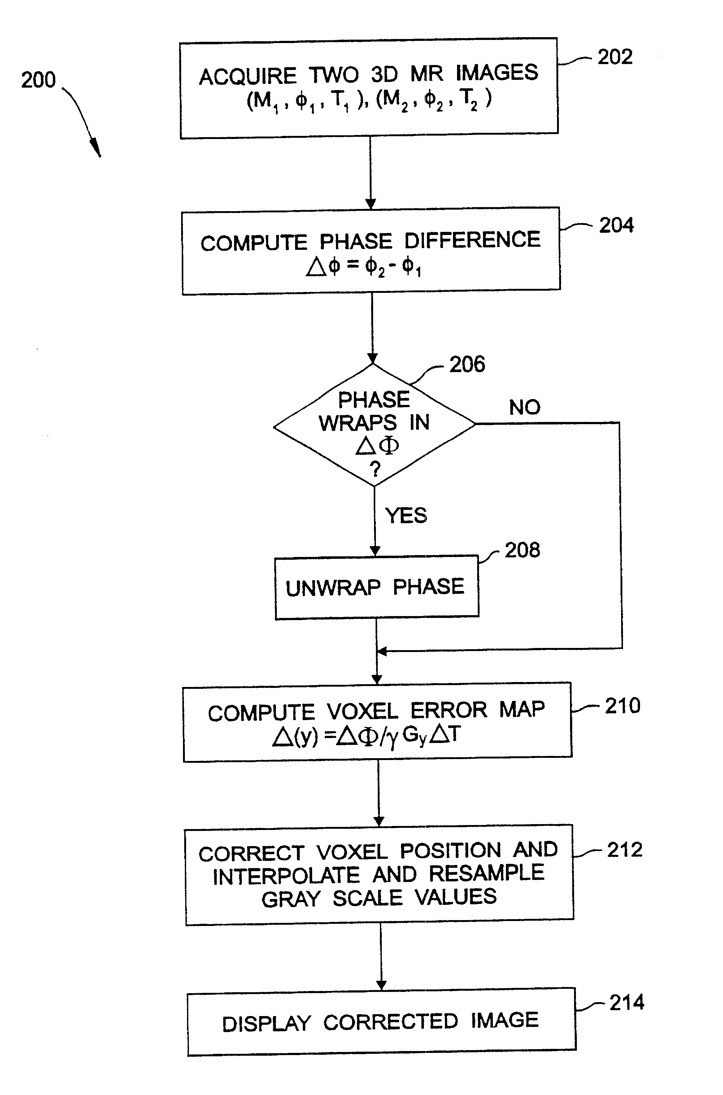
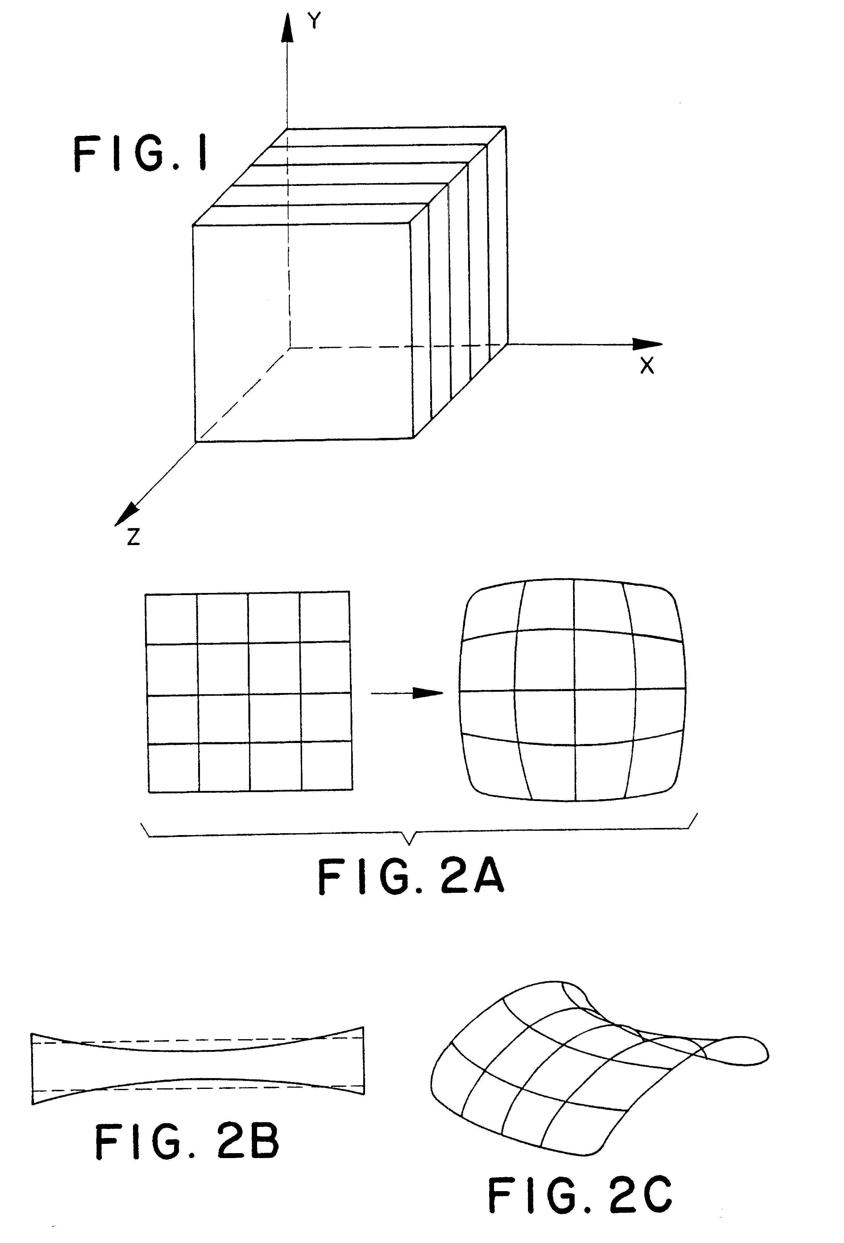
A three-dimensional (3D) magnetic resonance imaging (MRI) system performs object-induced geometric distortion correction.

Exemplary 3D MRI System

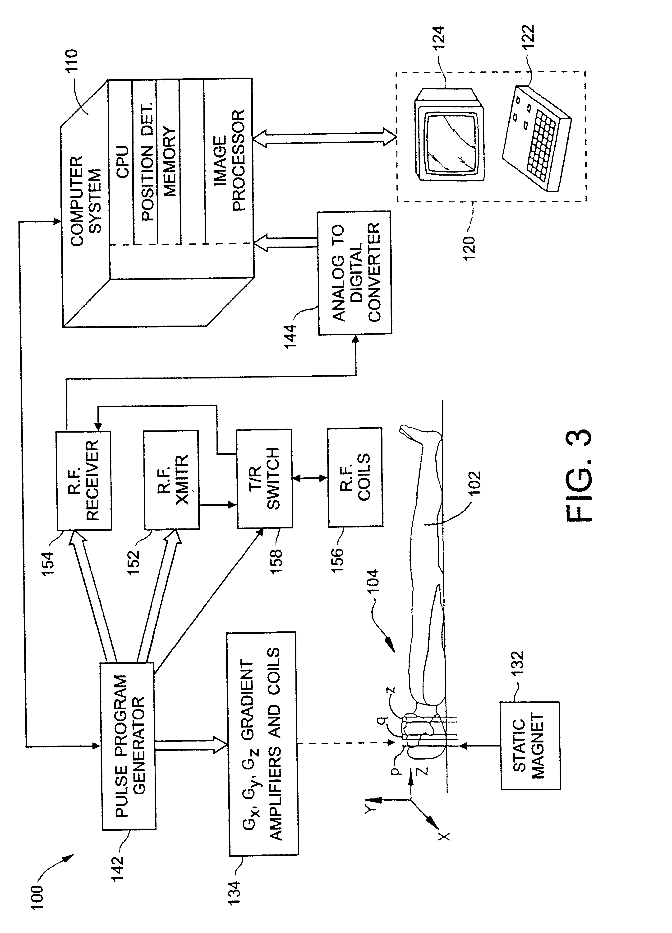
FIG. 3 illustrates an exemplary three-dimensional (3D) magnetic resonance imaging (MRI) system 100 for performing object-induced geometric distortion correction in accordance with the present invention.

The operation of 3D MRI system 100 is controlled by a computer system 110. A console 120 comprising a control panel 122 and a display 124 communicates with computer system 110 to enable an operator to control the production and display of 3D MR images on display 124.

To produce images with 3D system 100 at least a portion of a subject 102 of interest is placed within an examination region 104. A static magnet 132 produces a substantially uniform, temporally constant magnetic field B.sub.0 along a desired z-axis such that selected nuclear magnetic dipoles of subject 102 within examination region 104 preferentially align with the magnetic field. ...


PUM


Abstract

A three dimensional (3D) magnetic resonance imaging (MRI) system (100) performs object-induced geometric distortion correction. The MRI system performs (202) a 3D MRI pulse sequence to acquire a first 3D MR image of an examination region containing at least a portion of a subject and performs (202) the 3D MRI pulse sequence a second time to acquire a second 3D MR image of the examination region A computer system (110) computes (210) a voxel error map based on a phase difference between the first and second 3D MR images and corrects (212) voxel positions in one of the 3D MR images in accordance with the voxel error map.

Description

The present invention relates generally to the field of magnetic resonance imaging (MRI). More particularly, the present invention relates to the field of geometric distortion correction in MRI.Neurosurgical stereotaxis refers to a collection of techniques used to superimpose radiological volume images intra-operatively to the patient's skull, brain, and cerebrovasculature. Typical stereotactic procedures begin with the collection of a three dimensional (3D) computer tomography (CT) image containing fiducial markers. The resulting 3D image space may then be used to determine an optimal craniotomy or skull opening site and to model virtually the potential intra-operative orientation of a surgical tool, such as a biopsy needle for example. Using such images helps reduce the size of the craniotomy and intracranial traverse of surgical tools.For a typical procedure, a stereotactic frame or frameless fiducial imaging markers are mounted on the patient's head, often by screwing either int...

Claims


Application Information

Patent Timeline
IPC IPC(8): G01R33/54G01R33/565
CPCG01R33/4822G01R33/56563
Inventor DEAN, DAVIDDUERK, JEFFREY L.KAMATH, JANARDHAN K.
Owner CASE WESTERN RESERVE UNIV
Why Eureka
Try Eureka