
Debug mechanism for data processing systems

a data processing system and data processing technology, applied in software testing/debugging, program synchronisation, detecting faulty computer hardware, etc., can solve problems such as limiting the maximum performance of the data processing system during normal operation

Inactive Publication Date: 2002-09-03
ARM LTD
View PDF10 Cites 57 Cited by
  • Summary
  • Abstract
  • Description
  • Claims
  • Application Information

AI Technical Summary

Benefits of technology

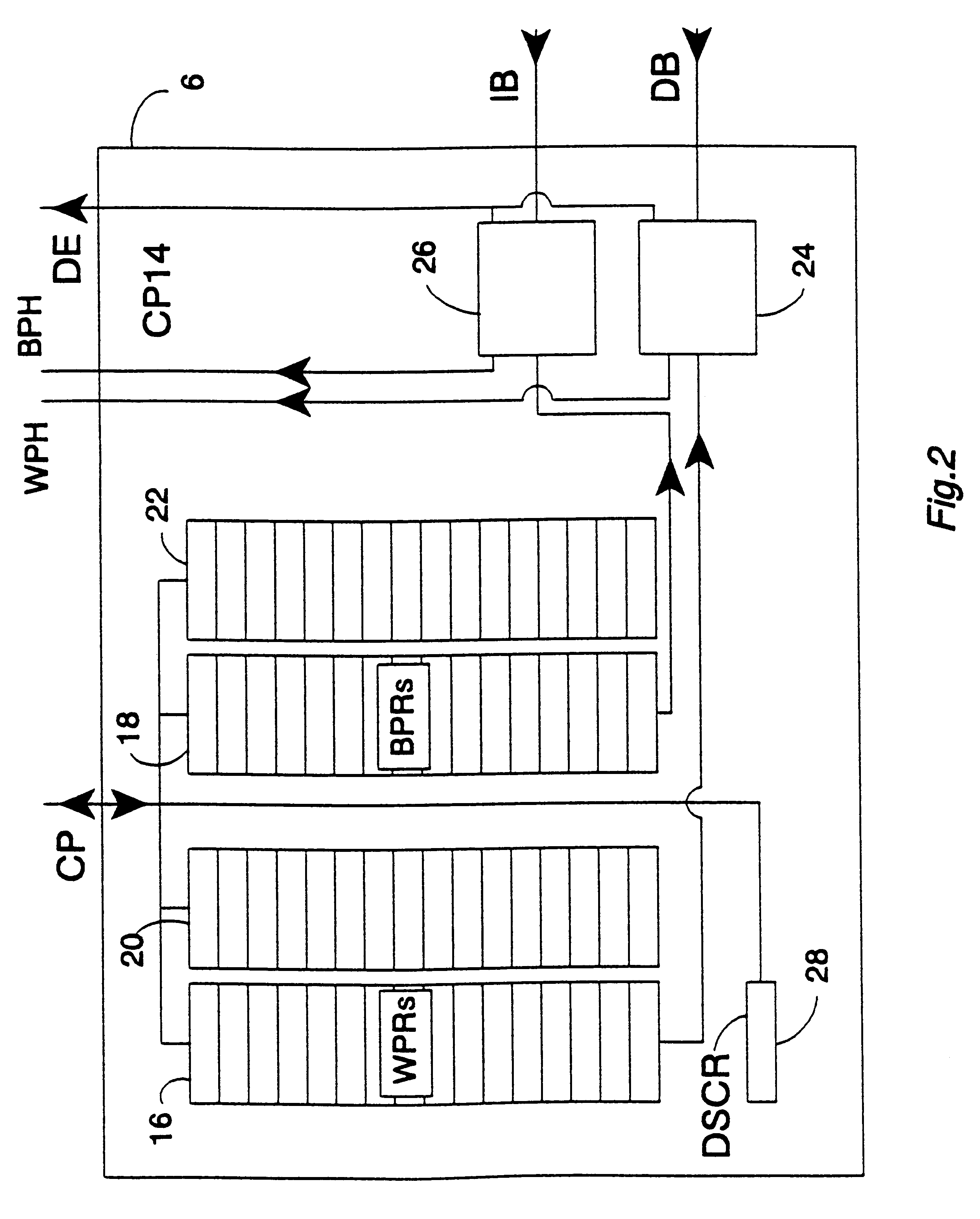
Control data associated with more sophisticated breakpoint and watchpoint operation, such as mask values, enable bits, and mode selection values, may also be efficiently programmed and stored using registers within the debug coprocessor. Accordingly, comparisons against address attributes such as the size of the transfer, the mode (e.g. priveleged / user), an instruction set indicating bit (the ARM Thumb T-bit), etc, may also be made.
In order to deal with the potential problems of the main processor or a coprocessor trying to access such a data value register at the same time that it was being accessed by the scan chain, preferred embodiments provide such a data value register in the form of two data value registers, one of these being writable by the main processor or a coprocessor and readable by a scan chain and the other of these being readable by the main processor or a coprocessor and writable by a scan chain. This effectively forms a bidirectional communications channel that avoids potential data conflicts.
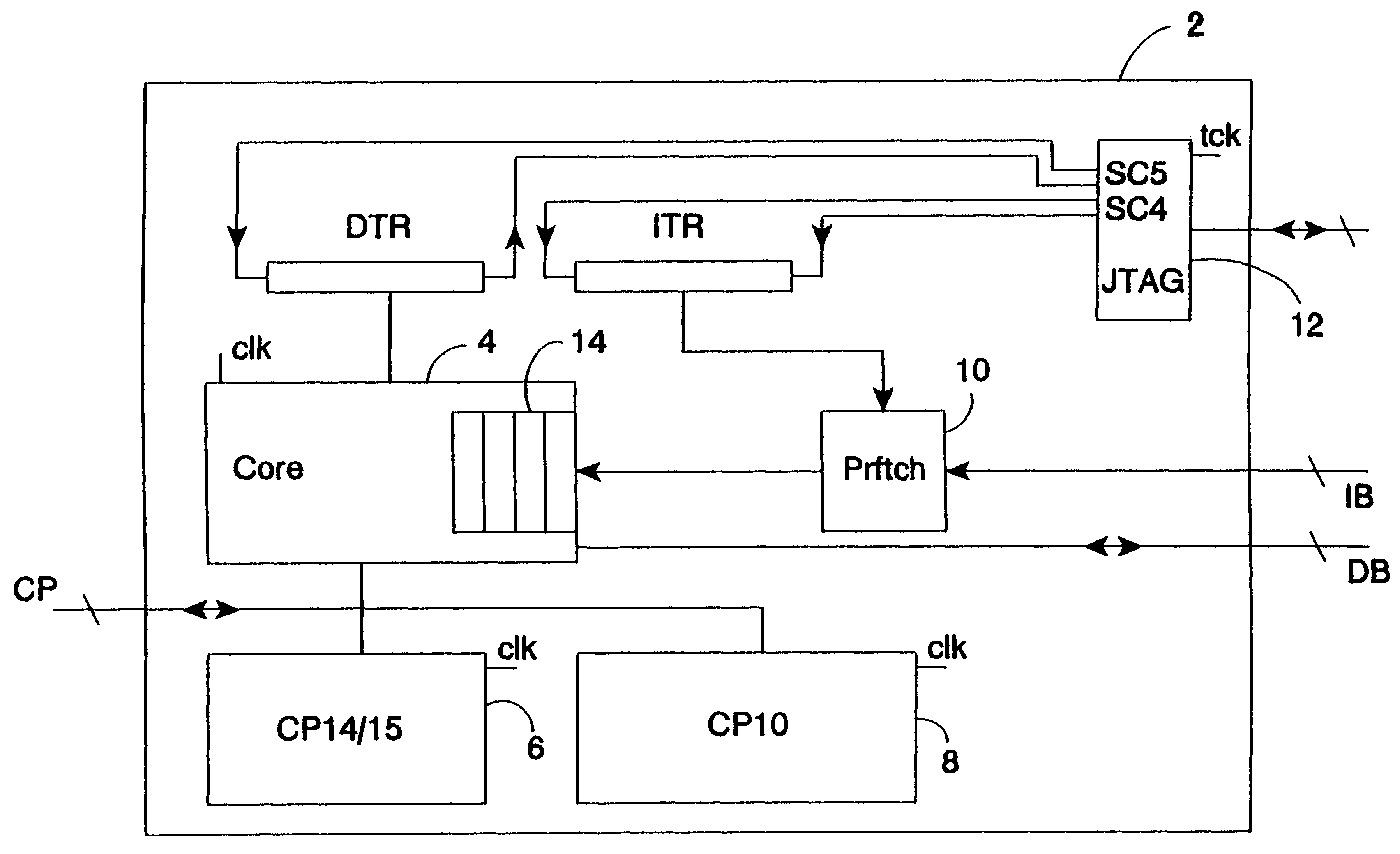
The debug coprocessor will typically operate at the same clock frequency as the main processor and any other coprocessors in the system. This facilitates the interactions between these elements using a standard coprocessor interface such that the debug coprocessor has a reduced impact upon the speed of normal operation of the main processor and any other coprocessors. However, the scan chain mechanisms will typically operate at a different, typically asynchronous, clock speed and so the debug coprocessor needs to include circuits that allow these elements within different clock domains to communicate. These extra mechanisms may be isolated within the debug coprocessor in a manner that avoids interference with the normal operation of the other main circuit elements.

Problems solved by technology

A problem with debugging mechanisms is that they should not interfere with or limit the performance possible during normal operation.
These additional circuit elements that are only needed for debug purposes can impose signal propagation delays within critical data paths that limit the maximum performance of the data processing system during normal operation.

Method used


Image

  • Debug mechanism for data processing systems
  • Debug mechanism for data processing systems
  • Debug mechanism for data processing systems

Examples


Embodiment Construction

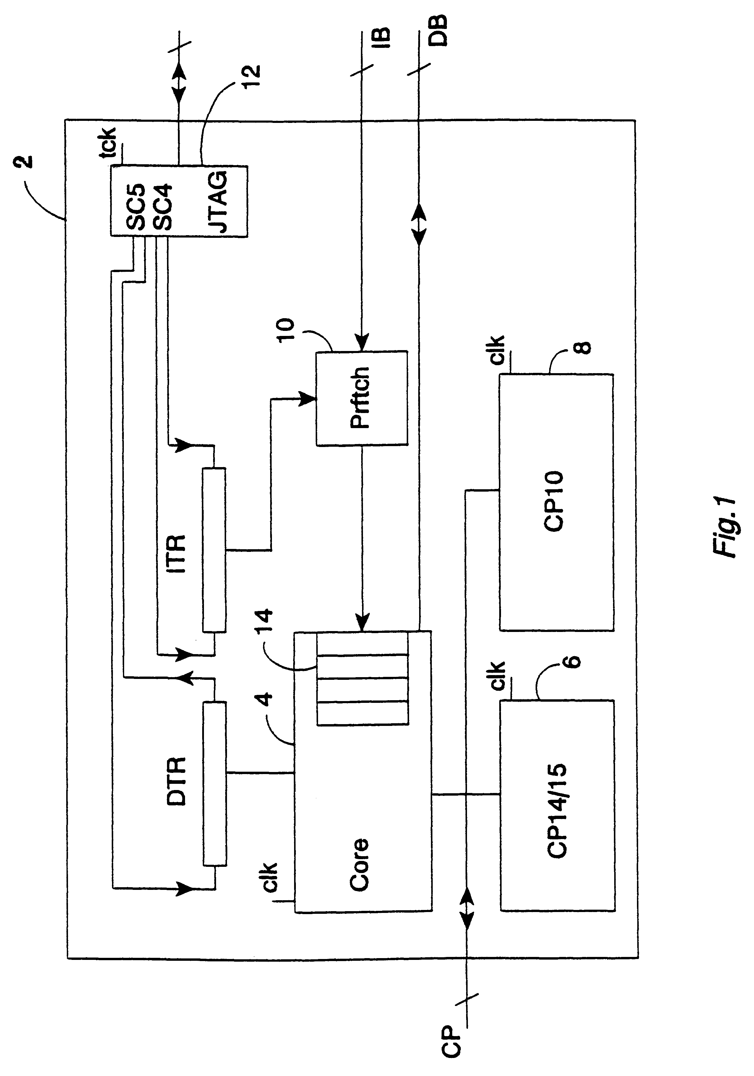
FIG. 1 shows a data processing system 2 that includes a main processor 4, a debug coprocessor (and system coprocessor) 6 and a floating point unit coprocessor 8. The main processor 2 is coupled via a coprocessor interface in the form of a coprocessor bus CP to the debug coprocessor 6 and the floating point unit coprocessor 8. The form of this coprocessor bus CP is substantially the same as a standard coprocessor bus, such as the ARM coprocessor bus (as used with microprocessors produced by ARM Limited of Cambridge, England).

The main processor 4 is coupled to a data bus DB and via a prefetch unit 10 to an instruction bus IB. The data bus DB and the instruction bus IB both include address portions that are monitored by the debug coprocessor 6 to identify breakpoints and watchpoints respectively.

The main processor 4, the debug coprocessor 6 and the floating point unit coprocessor 8 are all driven by a common main processor clock signal clk at a main processor clock frequency. A scan ch...


PUM


Abstract

Apparatus for processing data is provided, said apparatus comprising: a main processor 4 responsive to main processor instructions within a stream of instructions input to said main processor 4 to perform main processor operations; a coprocessor 6 coupled to said main processor 4 via a coprocessor interface CP and responsive to coprocessor instructions MCR, MRC within said stream of instructions to perform coprocessor operations; wherein said coprocessor 6 is a debug coprocessor operable to at least partially control generation of diagnostic data for debugging said apparatus for processing data and said coprocessor instructions are debug coprocessor instructions that control operation of said debug coprocessor. Using a debug mechanism in the form of a debug coprocessor reduces the impact of the debug mechanism upon normal operation.

Description

1. Field of the InventionThis invention relates to data processing systems. More particularly, this invention relates to debugging mechanisms for data processing systems.2. Description of the Prior ArtA problem with debugging mechanisms is that they should not interfere with or limit the performance possible during normal operation. As an example, known debugging mechanisms often involve the addition of multiplexers within the data processing paths to allow configuration of the debugging mechanisms, such as programming breakpoints and watchpoints. These additional circuit elements that are only needed for debug purposes can impose signal propagation delays within critical data paths that limit the maximum performance of the data processing system during normal operation.Viewed from one aspect the present invention provides an apparatus for processing data, said apparatus comprising:a main processor responsive to main processor instructions within a stream of instructions input to sa...

Claims


Application Information

Patent Timeline
IPC IPC(8): G06F11/36G06F9/52G06F9/38G06F11/22G06F11/28G06F15/16G06F15/177
CPCG06F11/3648
Inventor JAGGAR, DAVID VIVIANHOHL, WILLIAM ADAM
Owner ARM LTD
Learn More