Pre-mix nozzle and full ring fuel distribution system for a gas turbine combustor

Inactive Publication Date: 2002-09-10
ANSALDO ENERGIA SWITZERLAND AG
View PDF3 Cites 97 Cited by
  • Summary
  • Abstract
  • Description
  • Claims
  • Application Information

AI Technical Summary

Benefits of technology

In an alternate embodiment, a secondary fuel nozzle is provided that eliminates the separate diffusion nozzle for maintaining the pilot flame. The pilot flame nozzle in the alternate embodiment includes a premix chamber, where fuel and air are mixed upstream of the nozzle outlet that is used to maintain the pilot flame. The pilot flame nozzle system includes a fuel supply conduit and air supply conduits which feed into a premix chamber that is in fluid communication with the pilot flame outlet nozzle and swirler.
It is another object of this invention to provide an improved secondary fuel nozzle system for a two-stage, two-mode combustion turbine engine that has a separate premix annular distribution system for improving efficiency and ease of manufacturing using standard stock.

Problems solved by technology

Complying with these regulations can be difficult utilizing conventional diffusion burners where the natural gas fuel is introduced directly via a fuel nozzle into the combustion chamber where it is mixed with combustion air.
One of the problems with such a hybrid system is that the premix nozzles, being on radial arms or pegs, actually do not provide for a uniform distribution of air and fuel mixture and can act as a flame holder.
Again, such an integrated system does not provide for complete uniform premixing of air and fuel because of the structural layout of the peg-like fuel distribution arms which are integrated into the diffusion nozzle system.
In a typical operational cycle of a two-stage, two-mode gas turbine, fuel is delivered to the primary nozzles with air flow, which is ignited by spark plugs, causing ignition and fire in the primary combustion chambers.
Once the secondary pilot flame has been established and transfer fuel is flowing, fuel is shut off to the primary nozzle causing a flame-out in the primary combustion chambers.
The secondary nozzle has also been found to contribute to NOx pollution, especially when functioning as a diffusion nozzle.

Method used


Image

  • Pre-mix nozzle and full ring fuel distribution system for a gas turbine combustor
  • Pre-mix nozzle and full ring fuel distribution system for a gas turbine combustor
  • Pre-mix nozzle and full ring fuel distribution system for a gas turbine combustor

Examples


Embodiment Construction

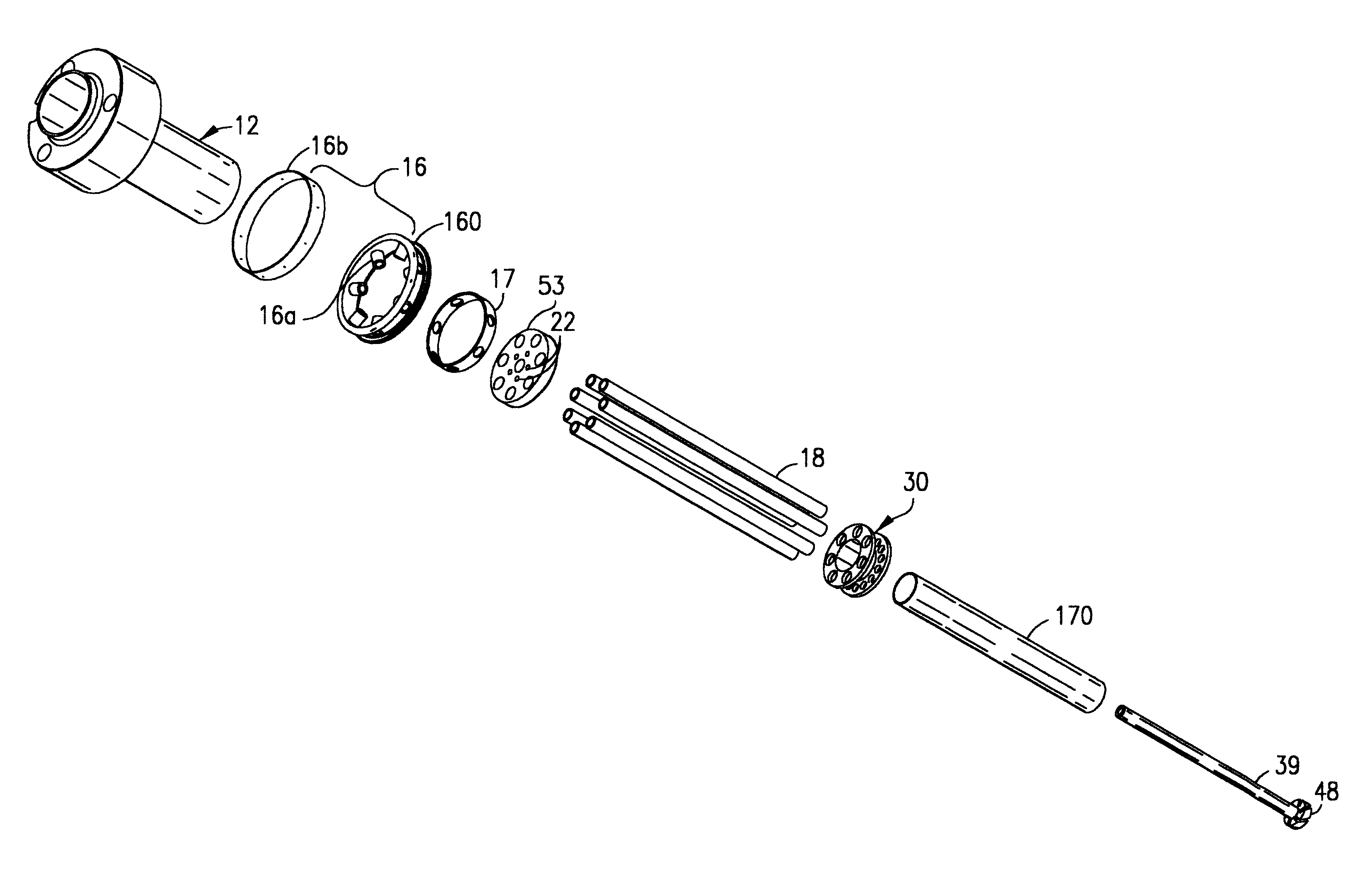
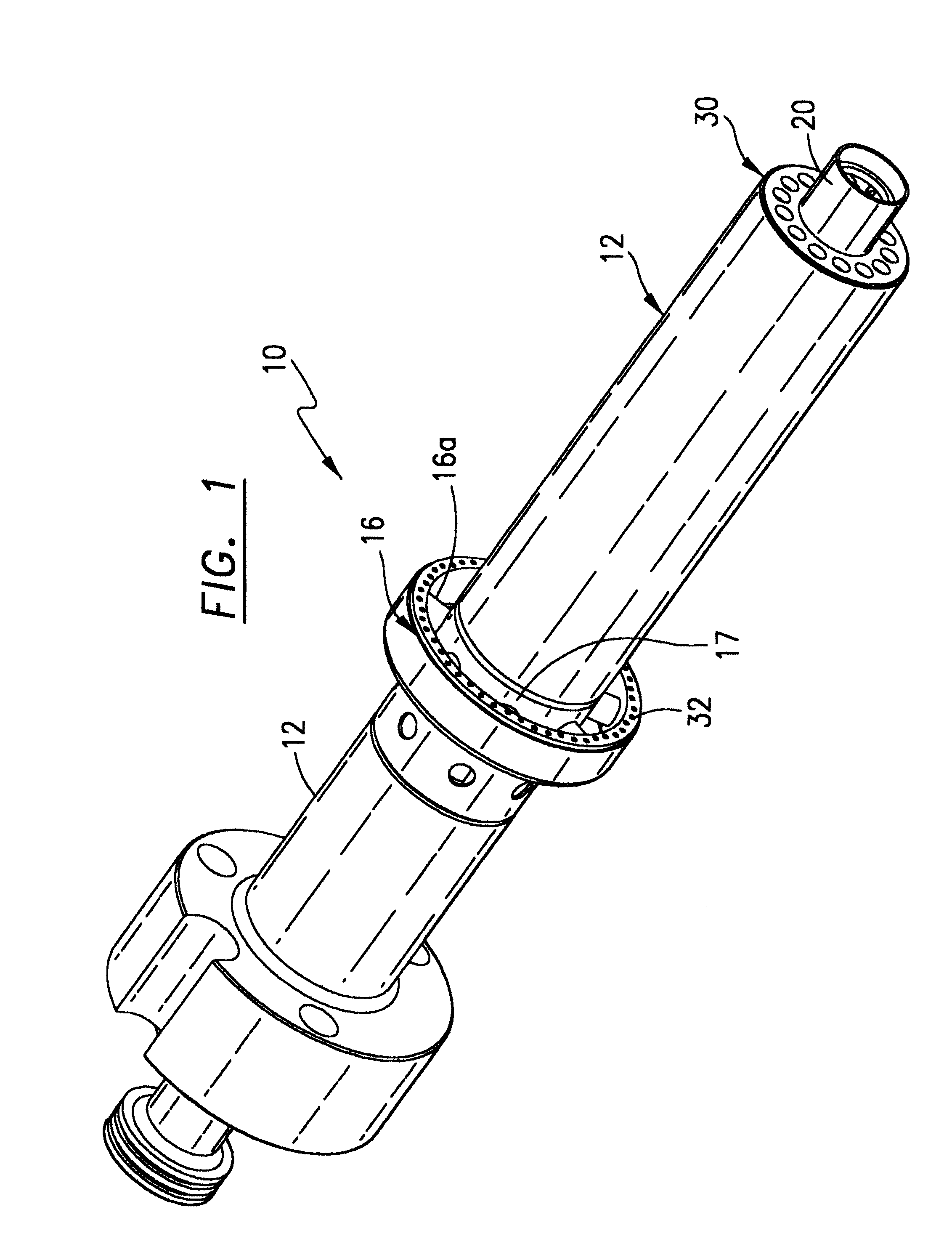
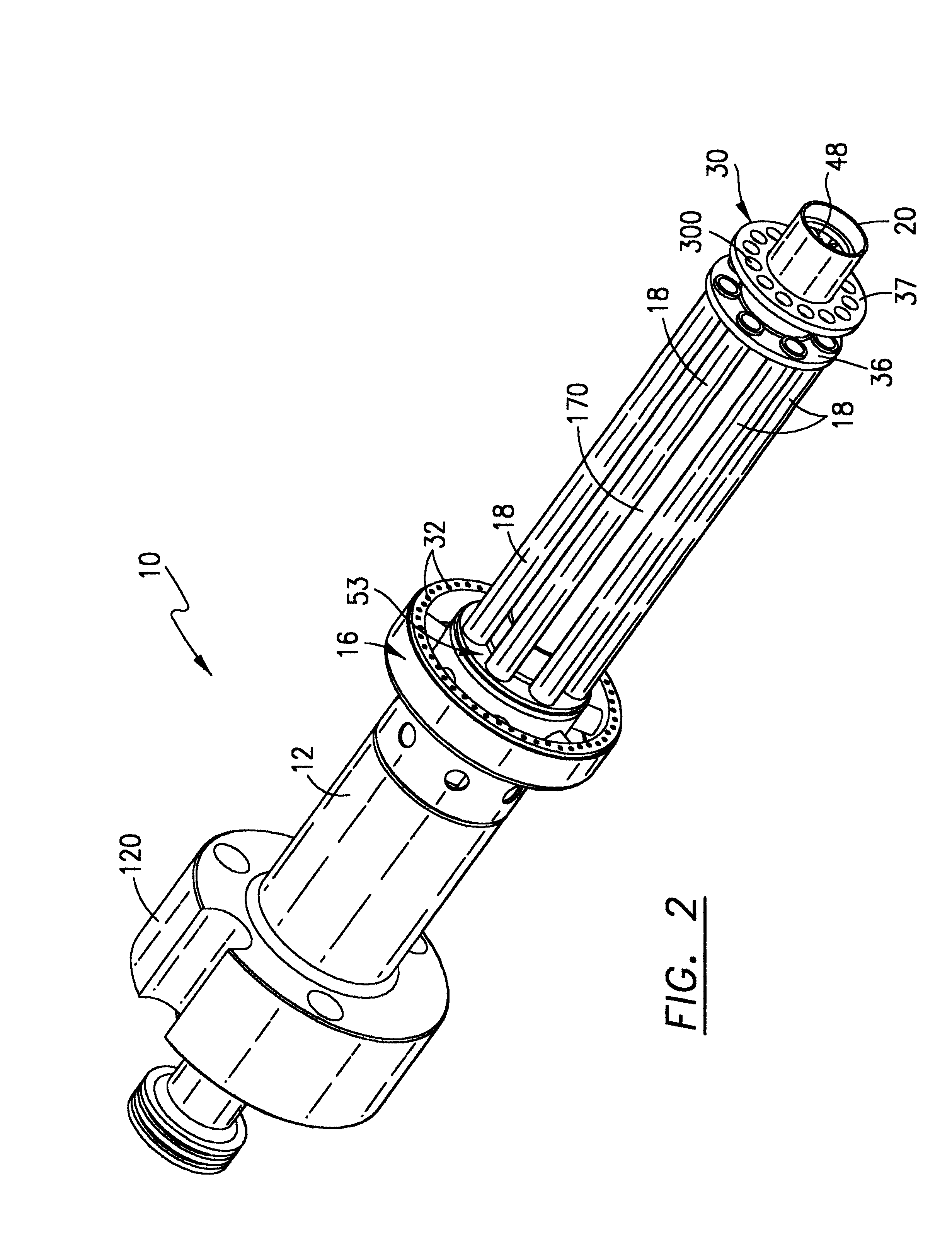
Referring now to the drawings, and in particular FIG. 1, an annular fuel distribution manifold 16 that is mounted by the present invention is shown generally at 10 comprising a support sleeve 17 and support cylinders 16a to a diffusion nozzle housing 12 that terminates at one end with a diffusion nozzle 20 that provides the diffusion pilot flame. Fuel such as natural gas is provided to the annular manifold 16 through the cylinders 16a and is dispensed from the annular manifold 16 through a plurality of numerous holes or apertures 32 in the downstream face of manifold 16 (facing toward the diffusion nozzle 20). The annular fuel distribution manifold 16 functions to premix fuel with air traveling downstream under pressure towards the diffusion nozzle 20 parallel to the elongated nozzle body 12 while the air stream surrounds the manifold 16 on all sides. The fuel, which is ejected under pressure from the numerous holes 32, is mixed into the air stream and is propelled downstream to the...


PUM


Abstract

A fuel nozzle system for use in a combustor utilized in a combustion turbine for reducing nitrogen oxides and other pollutants including an annular fuel distribution manifold separately mounted away from a diffusion nozzle, said annular manifold having a plurality of fuel emitting passages or holes disposed along the downstream side of the manifold, said manifold being mounted in a position away from the diffuser nozzle body to allow air to stream around the manifold on all sides allowing for a thorough mixture of fuel and air around the annular manifold for better premixing in the combustion chamber. In an alternate embodiment, the diffusion nozzle is replaced by a pilot flame nozzle that is supplied with both air and fuel through a premix air and fuel chamber to a pilot flame nozzle which is used to sustain combustion in the secondary chamber. The use of a pilot flame nozzle that has a fuel and air mixture is believed to reduced NOx emissions.

Description

1. Field of the InventionThis invention relates generally to a fuel and air distribution system for use in a gas turbine combustor for reducing the production of nitrogen oxide and other air pollutants and specifically to a premix fuel nozzle for use in the combustion chambers for gas turbine combustors.2. Description of Related ArtThe U.S. Government has enacted requirements for lowering pollution emissions, and in particular, for lowering the amounts of nitrogen oxide (NOx) and carbon monoxide produced by natural gas powered turbines, which in turn generate electricity by being connected to electrical generators. The combustion process of air and natural gas as a fuel in a gas turbine combustion chamber produces pollutants such as nitrogen oxides, which are both NO and NO2, designated generally as NOx.The U.S. Government has enacted requirements for lowering pollution emissions, especially for lowering the NOx produced by gas turbines during power generation. Complying with these ...

Claims


Application Information

Patent Timeline
IPC IPC(8): F23R3/28F23R3/34
CPCF23R3/286F23R3/343F23D2900/00008F23D2900/00015
Inventor KRAFT, ROBERT J.MARTLING, VINCENT C.MACK, BRIAN R.
Owner ANSALDO ENERGIA SWITZERLAND AG
Why Eureka
Try Eureka