
Method for quantifying the texture homogeneity of a polycrystalline material

a polycrystalline material and texture homogeneity technology, applied in material analysis using wave/particle radiation, instruments, nuclear engineering, etc., can solve the problems of inability to identify the presence of texture homogeneity within the sample, and visual representations of texture can only provide a general idea of texture homogeneity

Inactive Publication Date: 2002-10-08
CABOT CORP
View PDF1 Cites 45 Cited by
  • Summary
  • Abstract
  • Description
  • Claims
  • Application Information

AI Technical Summary

Benefits of technology

Additional features and advantages of the present invention will be set forth in part in the description that follows, and in part will be apparent from the description, or may be learned by practice of the present invention. The objectives and other advantages of the present invention will be realized and attained by means of the elements and combinations particularly pointed out in the description and appended claims.

Problems solved by technology

While conventional diffraction techniques can be used to adequately determine the bulk texture of materials, they are incapable of identifying the presence of texture inhomogeneities within the sample.
However, visual interpretation of an IPF provides a very subjective description of the texture character of the samples.
Also, visual representations of texture can only provide a general idea as to texture homogeneity.

Method used


Image

  • Method for quantifying the texture homogeneity of a polycrystalline material
  • Method for quantifying the texture homogeneity of a polycrystalline material
  • Method for quantifying the texture homogeneity of a polycrystalline material

Examples


example 1

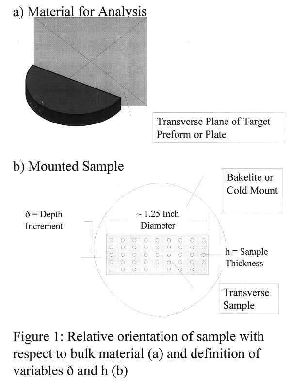
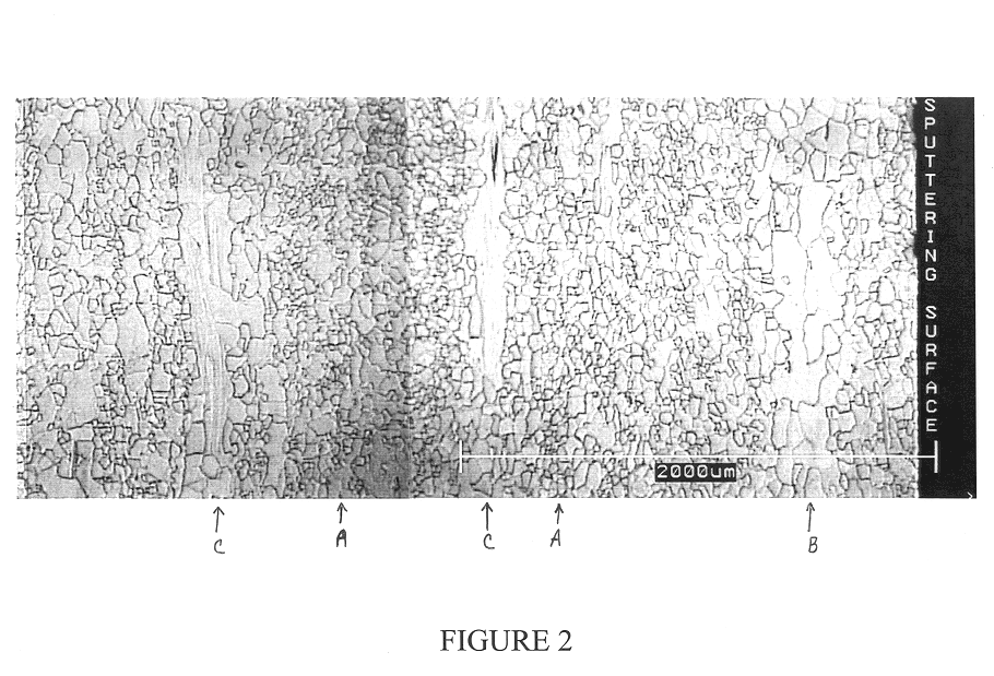
This experiment was conducted to demonstrate the correlation between microstructural and textural inhomogeneities within a tantalum plate of poor metallurgical quality. Sputtering target-grade wrought and recrystallized 0.25" thick tantalum plate was obtained on the commercial market. Results of chemical, metallurgical, and mechanical properties are provided in Table 1. A sample approximately 0.25".times.1.0".times.0.5" was removed from a region approximately 0.5" or more away from any sheared edge of the plate. The sample was mounted, and the transverse face of the sample of the sample was ground, polished, and etched. The texture samples were prepared in accordance with the procedure described in C. A. Michaluk, C. Heubeck, and H. Klein, Methodologies for Determining the Global Texture of Tantalum Plate Using X-Ray Diffraction, Tantalum, (E.chem. et al., eds), TMS, Warrendale, Pa. (1996) pp 123-131, incorporated in its entirety herein by reference, with the exception that the as-p...

example 2

This analysis was conducted to determine values of .OMEGA. and .LAMBDA. for tantalum deemed unacceptable for use as a sputtering target. FIG. 7 shows a section of a tantalum sputtering target that the user rejected because it produced films with unacceptable variation in thickness (i.e. >5%). The eroded surface of the rejected target had large regions having a matte finish intermixed with areas having a lustrous finish. Texture analysis revealed that the matte surfaces contained a mixed (111)-(001) texture while the texture of lustrous regions was nearly entirely (001). It is been reported that the matte regions represent material that was readily eroded by sputtering, whereas the lustrous areas were resistant to sputter erosion, indicating that localized regions having a prominent (001) within a tantalum sputtering target are detrimental to sputtering performance (C. A. Michaluk, D. B. Smathers, and D. P. Field, Affect of Localized Texture on the Sputtering Performance of Tantalum,...

example 3

This example determines values of .OMEGA. and .LAMBDA. for a tantalum sputtering target that exhibited desirable sputtering performance, as well as for a tantalum target that had marginal sputtering performance. Photographs of the desirable and marginal performing sputtering targets are shown in FIGS. 12 and 13, respectively. Normal-orientation IPF maps from transverse sections of the desirable and marginal performing targets are presented in FIGS. 14 and 15, respectively. Samples had been prepared and analyzed using the procedures described in Example 1.

The texture homogeneity parameters of the desirable and marginal performing tantalum targets are reported below:

Based on the results from Example 2, tantalum material having values of .OMEGA. and .LAMBDA. less than or equal to 74.73 / mm and 4.993 / mm, respectively, are best suitable for sputtering target applications.


PUM

PropertyMeasurementUnit
Lengthaaaaaaaaaa
Lengthaaaaaaaaaa
Lengthaaaaaaaaaa

Abstract

A method for quantifying the texture homogeneity of a polycrystalline material is described. The method involves selecting a reference pole orientation; scanning in increments a cross-section of the polycrystalline material having a thickness with scanning orientation imaging microscopy or other measuring technique to obtain actual pole orientations of a multiplicity of grains throughout the cross-section of the polycrystalline material. The orientation differences between the reference pole orientation and actual pole orientations of a multiplicity of grains is then determined. A value of misorientation from the reference pole orientation at each grain measured throughout the thickness is then assigned. The average misorientation of each measured increment throughout the thickness is then determined. A texture gradient and / or texture banding can then be obtained by determining the first and / or second derivative, respectively, of the average misorientation of each measured increment through the thickness of the sample used for evaluation. A method to predict the sputtering efficiency of a target is also described as well as a system for quantifying the texture homogeneity of a polycrystalline material.

Description

The present invention relates to the texture of polycrystalline materials and further relates to methods of determining or quantifying the texture homogeneity of polycrystalline materials. The present invention further relates to sputtering targets and determining sputtering efficiencies in sputtering targets.Certain properties of polycrystalline materials, including deformation behavior, magnetic permeability, corrosion rate, and resistance to electromigration are generally dependent on the arrangement of atoms within the material (J. A. Szpunar, Texture Design for New Application, Proceeding of the Twelfth International Conference on Textures of Materials, J. A. Szpunar (ed.), NRC Research Press, Ottawa, pp. 6, 1999), incorporated in its entirety herein by reference. Often, the processes utilized to manufacture wrought metals and alloys impart a preferred orientation to the individual crystallites in the material. Crystallographic texture refers to the alignment of atomic planes w...

Claims


Application Information

Patent Timeline
IPC IPC(8): C23C14/34G01N23/20G01N33/20G01Q30/02
CPCC23C14/3414H01J37/34G01N33/20
Inventor MICHALUK, CHRISTOPHER A.FIELD, DAVID P.
Owner CABOT CORP
Learn More