Zero voltage switching power conversion circuits

Inactive Publication Date: 2002-10-08
TECHN WITTS
View PDF5 Cites 51 Cited by
  • Summary
  • Abstract
  • Description
  • Claims
  • Application Information

AI Technical Summary

Benefits of technology

The subject invention uses a reset capacitor, an auxiliary switch, and a small inductor to accomplish ZVS in a tapped inductor buck converter and simultaneously to achieve non-pulsating input and output currents. Adaptive gate drive circuits are also revealed that achieve optimal switch timing of the power mosfets. Adaptive gate drive circui

Problems solved by technology

The amount of dead time required is dependent on the current magnitudes and component values so that the chosen dead time is often close to the amount of dead time needed for a range of currents but often the fixed dead time results in additional losses because the switch is turned on too soon when there is applied voltage to the switch or too late after the switch body diode or other parallel diode has been conducting for a time and dissipating power at a rate greater than the switch would dissipate if it were turned on at the best possible time.
One significant source of power losses in high frequency power converters

Method used


Image

  • Zero voltage switching power conversion circuits
  • Zero voltage switching power conversion circuits
  • Zero voltage switching power conversion circuits

Examples


Embodiment Construction

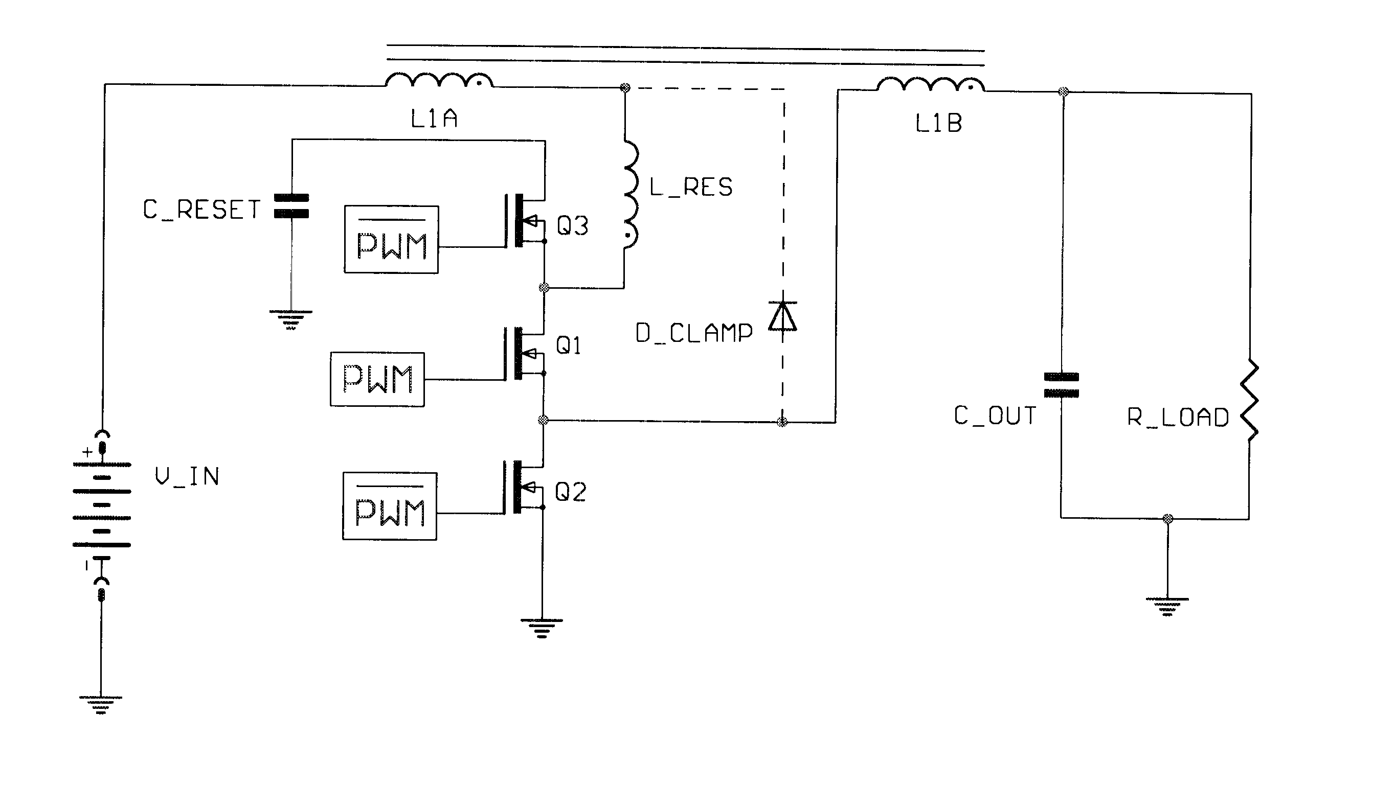
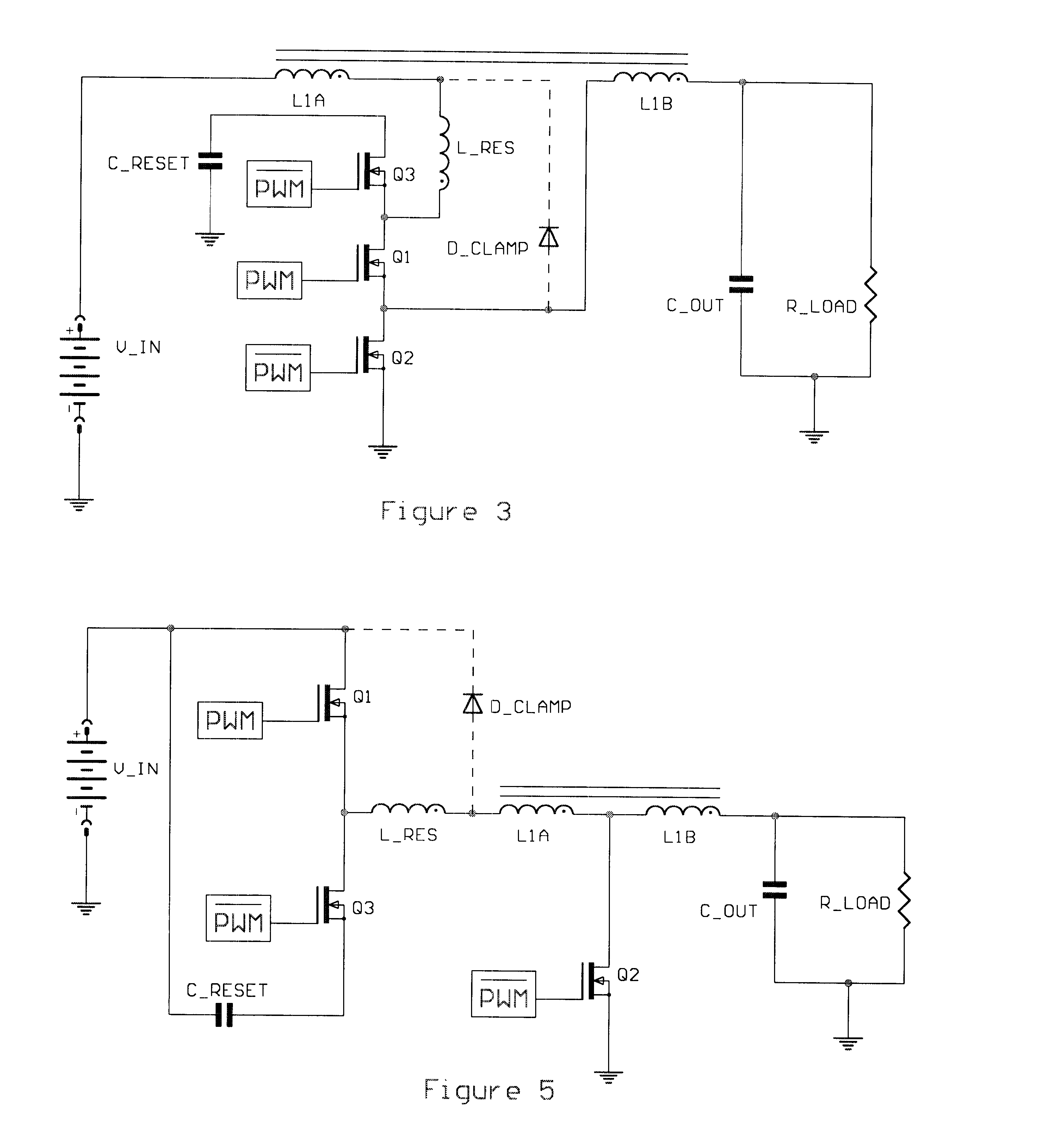
FIG. 3 illustrates the ZVS tapped inductor buck converter of the subject invention. In addition to achieving ZVS for all switches the converter also achieves non-pulsating or continuous input and output terminal currents. The FIG. 3 circuit uses a ZVS cell first revealed in a pending patent whose Ser. No. is 09 / 956,711. The ZVS cell comprises a main switch, an auxiliary switch. a small auxiliary inductor, and a capacitor. By substituting the ZVS cell for the main switch in a hard switching power converter circuit the new circuit with the new ZVS cell can achieve non-pulsating terminal currents and elimination of first order switching losses.

Referring to FIG. 3, during an initial condition and on state of the circuit, main switch Q1 is on and switches Q2 and Q3 are off, current flows from the source, V_IN, through the winding L1A, through the small auxiliary inductor, L_RES, through the switch Q1, through the winding L1B, to the output terminal and the load. During the Q1 switch on t...


PUM


Abstract

A tapped inductor buck converter which achieves zero voltage switching and continuous input and output terminal currents is revealed. To achieve these results an additional switch, a small inductor, and a capacitor are required. The small inductor serves as a source of energy for driving the critical turn on transition of the main switch and the same small inductor also serves as a filter component for smoothing the input and output terminal currents. Simple adaptive gate drive circuits are revealed that improve the timing for turn on of zero voltage switches and reduce gate drive losses. A synchronous rectifier self drive mechanism is revealed which is universally applicable to zero voltage switching power converters with a single main switch which rely on an auxiliary inductor to drive the critical turn on transition of the single main switch. The wave form generated by the auxiliary inductor is ideally suited to synchronous rectifier self drive. Finally, peak current sensing techniques are revealed which are universally applicable to zero voltage switching power converters with a single main switch and an auxiliary switch which rely on an auxiliary inductor to drive the critical turn on transition of the single main switch. The current sensing techniques sense a winding voltage of the auxiliary inductor during the on time of the auxiliary switch. The winding voltage is directly related to the peak current in the main winding of the auxiliary inductor and the peak current in the single main switch of the power converter. The novel current sensing techniques are low noise, reliable, and lossless.

Description

1. Field of the InventionThe subject invention generally pertains to electronic power conversion circuits, and more specifically to high frequency, switched mode power electronic converter circuits. The subject invention is a continuation of a pending patent whose Ser. No. is 09 / 956,711, filed Sep. 19, 2001.2. Description of Related ArtFor power converter applications that require large step down ratios, such as providing power to a microprocessor or DSP core, there are several possible solutions. In some cases an isolated converter form such as a forward converter is chosen so that the transformer can be used to provide the voltage step down and current step up. Compared to a simple buck converter the forward converter. or any other isolated converter type requires considerably more silicon for the same power losses. It is well known to those who are skilled in the art of power converter design that the component load factor for any isolated converter is four times that of a simple...

Claims


Application Information

Patent Timeline
IPC IPC(8): H02M3/04H02M3/158H02M3/24H02M3/335H03K17/13H03K17/30H02M1/08H02M3/155H02M1/34
CPCH02M1/34H02M3/158H02M3/335H02M3/33538H03K17/133H03K17/302H02M1/08H02M3/155H02M2001/342Y02B70/1491H02M1/44H02M1/342Y02B70/10
Inventor WITTENBREDER, ERNEST H.
Owner TECHN WITTS
Why Eureka
Try Eureka