Aircraft and torque transmission

a technology of torque transmission and transmission shaft, which is applied in the direction of vertical landing/take-off aircraft, aircraft navigation control, aircraft gearing, etc., can solve the problems of inability of torque transmission to transmit engine output simultaneously to propellers and rotors, and aircraft become very unstabl

Inactive Publication Date: 2002-10-22
HOSODA ROKURO
View PDF5 Cites 141 Cited by
  • Summary
  • Abstract
  • Description
  • Claims
  • Application Information

AI Technical Summary

Problems solved by technology

The time required for the transition from the helicopter mode to the fixed wing mode or the other way around is more than ten-odd seconds, thus causing a problem in that the aircraft becomes very unstable during the transition.
(b) Prior art torque transmissions for VTOL aircraft serve to transmit engine output to propellers or rotors, but do not serve to transmit engine output simultaneously to propellers and rotors.
However, prior art torque transmissions cannot transmit engine output simultaneously to propellers and rotors.

Method used


Image

  • Aircraft and torque transmission
  • Aircraft and torque transmission
  • Aircraft and torque transmission

Examples


first embodiment

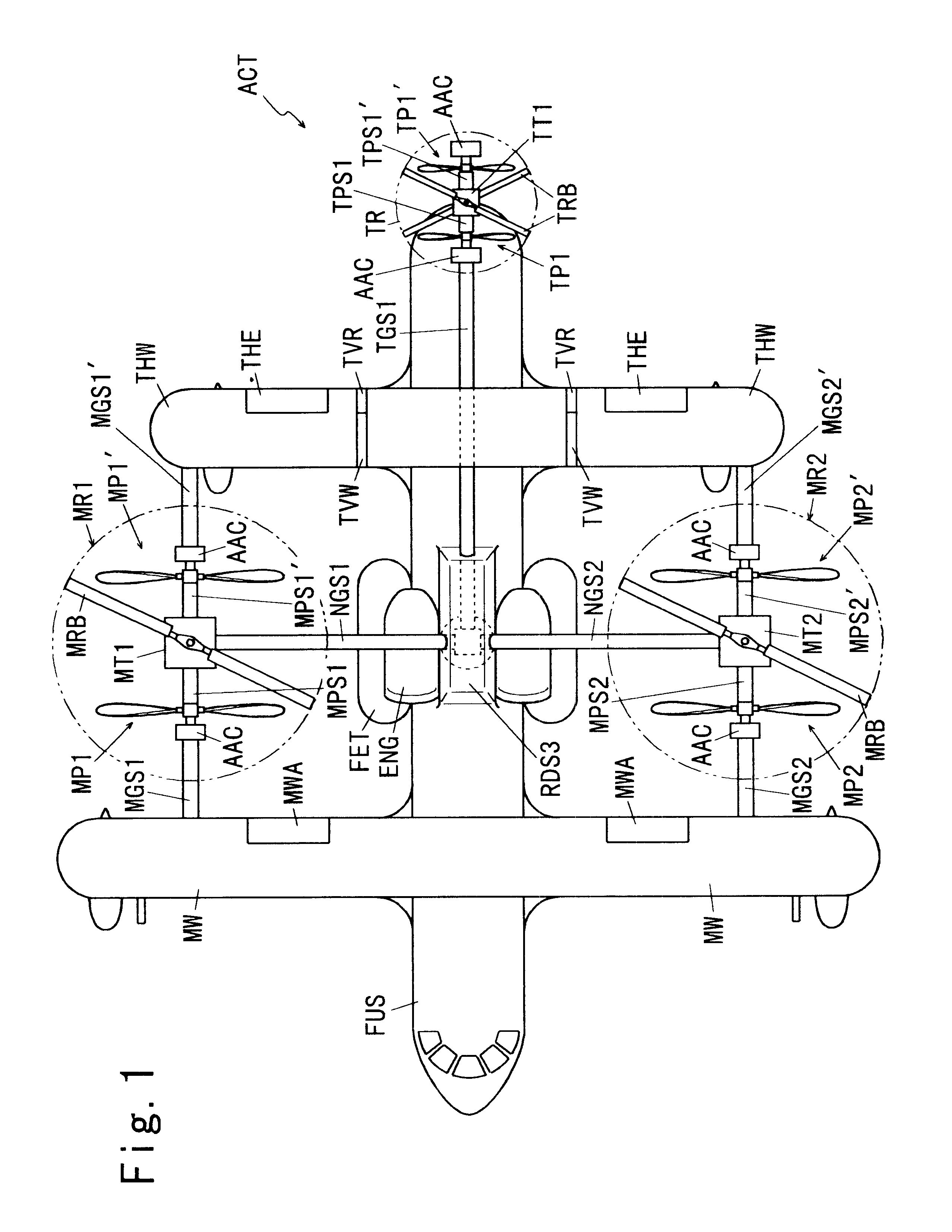
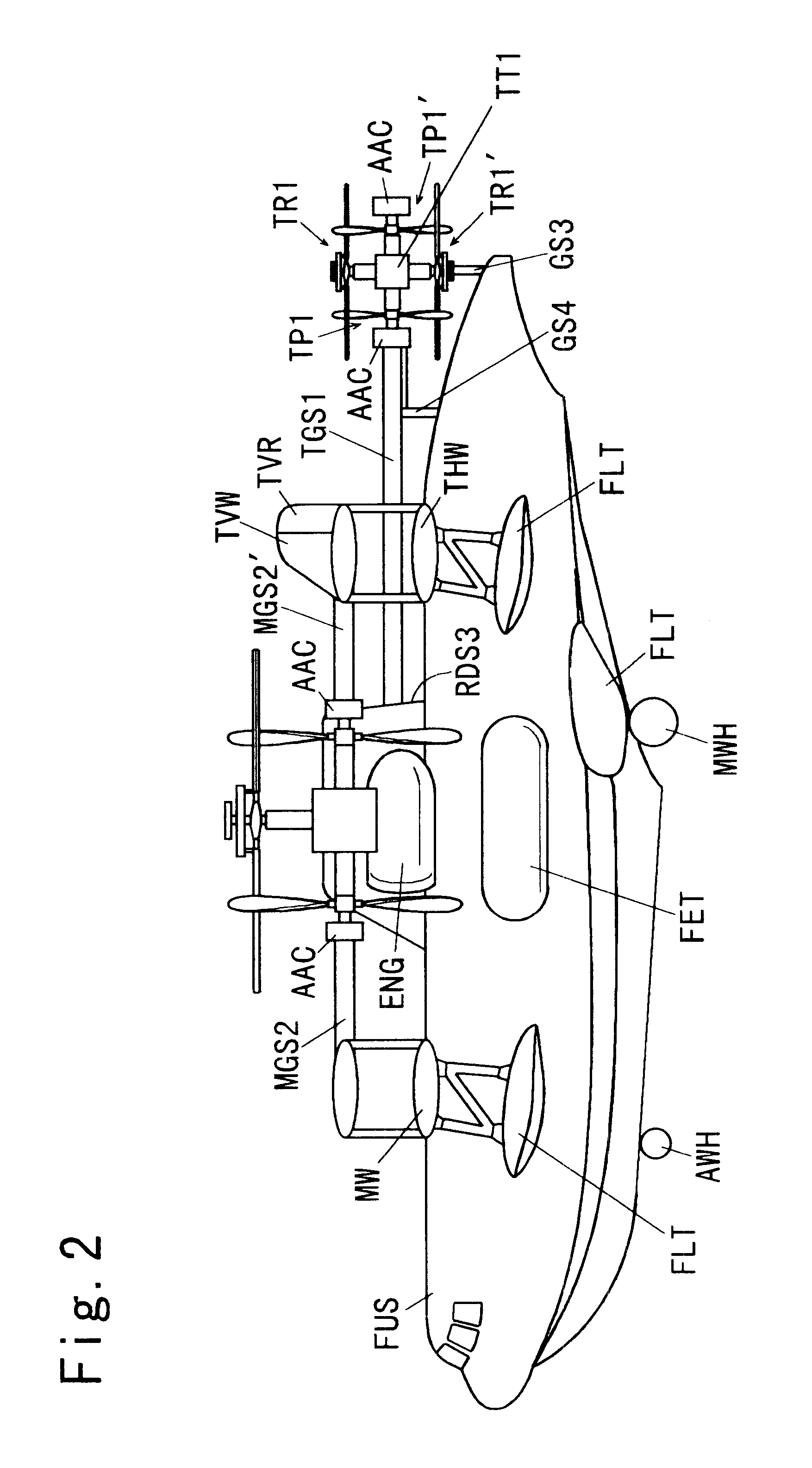
As shown in FIGS. 1 through 3, the aircraft of the first embodiment comprises:

a main wing MW which includes two ailerons MWA and is installed laterally in the fore part of a fuselage;

a horizontal tail wing THW which includes two horizontal tail elevators THE and is installed laterally in the rear part of the fuselage;

a vertical tail wing TVW which includes a vertical tail rudder TVR and is installed in the rear part of the fuselage;

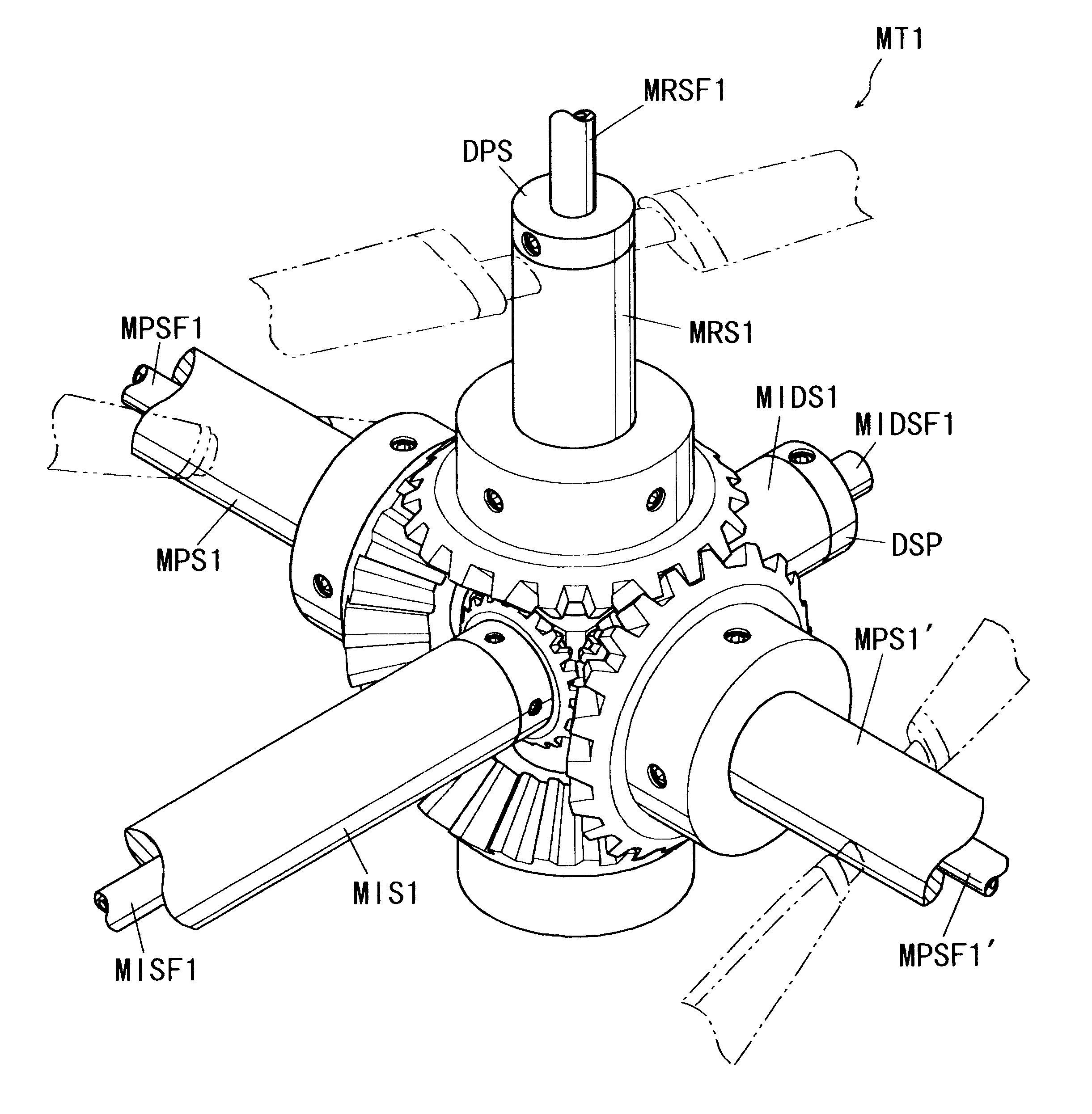
a main rotor MR 1 and main propellers MP 1 and MP 1' all of which are installed on a main propeller-rotor torque transmission MT1 retained at a position between the right-hand section of the main wing MW and the right-hand section of the horizontal tail wing THW;

a main rotor MR 2 and a main propellers MP 2 and MP 2' all of which are installed on a main propeller-rotor torque transmission MT 2 retained at a position between the left-hand section of the main wing MW and the left-hand section of the horizontal tail wing THW; and

tail rotors TR 1 and TR 1' and...

second embodiment

The second embodiment differs from the first embodiment in the following respects, but is constructed similarly to the first embodiment in all the other respects.

The aircraft of the second embodiment differs from the aircraft of the first embodiment in the following respects.

(1) The main propellers MP 1 and MP 2 are located at a longitudinal position aft of the main wing MW and forward of the planes of rotation of the main rotors MR 1 and MR 2 for the purpose of preventing the planes of rotation of the main propellers from intermeshing with the planes of rotation of the main rotors.

(2) The main propellers MP 1' and MP 2' are located at a longitudinal position forward of the horizontal tail wing THW and aft of the planes rotation of the main rotors MR 1 and MR 2 for the same purpose that is stated in item (1) above.

Functioning of the Second Embodiment

Since the planes of rotation of the main propellers MP 1, MP 1', MP 2 and MP 2' do not intermesh with the planes of rotation of the mai...

third embodiment

The third embodiment differs from the above-mentioned second embodiment in the following respects, but is constructed similarly to the second embodiment in all the other respects.

The aircraft of the third embodiment differs from the aircraft of the second embodiment in the following respects.

(1) The main propellers MP 1 and MP 2 are located at a longitudinal position forward of the main wing MW, and the main propellers MP 1' and MP 2' are located at a longitudinal position aft of the horizontal tail wing THIW for the purpose of preventing the planes of rotation of the main propellers MP 1, MP 1', MP 2, and MP 2' from intermeshing with the planes of rotation of the main rotors MR 1 and MR 2.

(2) Wires 7 for servomotor drive and wires 8 for servomotor control (see FIG. 19), all of which are routed from the cockpit to send driving current and control signals to the blade pitch angle controllers AAC for the main propellers MP 1 and MP 2, are introduced into the above-mentioned blade pitc...


PUM


Abstract

An aircraft including an airframe having a fuselage which extends longitudinally, and having fixed wings including a main wing, a horizontal tail wing and a vertical tail wing. A propeller-rotor torque transmission has a bevel gear which transmits the rotation of an input shaft simultaneously to a propeller shaft and to a rotor shaft. An engine gearbox supplies the above-mentioned input shaft with rotationalal motive power. The aircraft further includes a propeller collective pitch controller, a rotor collective pitch controller, an engine power controller which controls the output of the above-mentioned engine gearbox for the purpose of changing the rotational speed of the input shaft, and a flight control system having a directional (yaw) control system which controls the flight direction of the aircraft by controlling the positions of the above-mentioned control surfaces.

Description

1. Field of the InventionThe present invention relates to a vertical takeoff and landing aircraft or a short takeoff and landing aircraft (hereinafter referred to as a V / STOL aircraft as well) and to a torque transmission. The present invention may be favorably applied to an aircraft which uses bi-blade rotors and bi-blade variable pitch propellers.2. Description of the Prior Art(a) As regards prior art V / STOL aircraft, prototypes of a number of tilt rotor aircraft have been manufactured since the 1950s. Typically, in the case of such an aircraft, wings equipped with propellers and engines is tilted with respect to the fuselage, or propellers equipped with engines are tilted, to direct the thrust upward, thereby performing vertical takeoff and landing similarly to helicopters. In the case of a prior art tilt rotor aircraft as mentioned above, flight is performed such that propellers equipped with engines are turned upward when a vertical takeoff or a vertical landing is made (in the...

Claims


Application Information

Patent Timeline
Patent Type & Authority Patents(United States)
IPC IPC(8): B64C27/26B64C27/22B64C39/08B64C27/14B64C27/00B64D35/00B64D35/04B64C39/00B64C35/00
CPCB64C27/14B64C27/22B64C27/26B64C39/08B64D35/04B64C35/00Y10T74/19088Y10T74/19688
Inventor HOSODA, ROKURO
Owner HOSODA ROKURO
Why Eureka
Try Eureka