

Cushioned back carpet
a back carpet and carpet technology, applied in the field of carpets, to achieve the effect of reducing stress, facilitating subsequent printing operations, and facilitating melting adhesion
Inactive Publication Date: 2002-10-22
MILLIKEN & CO
View PDF107 Cites 79 Cited by
- Summary
- Abstract
- Description
- Claims
- Application Information
AI Technical Summary
Benefits of technology
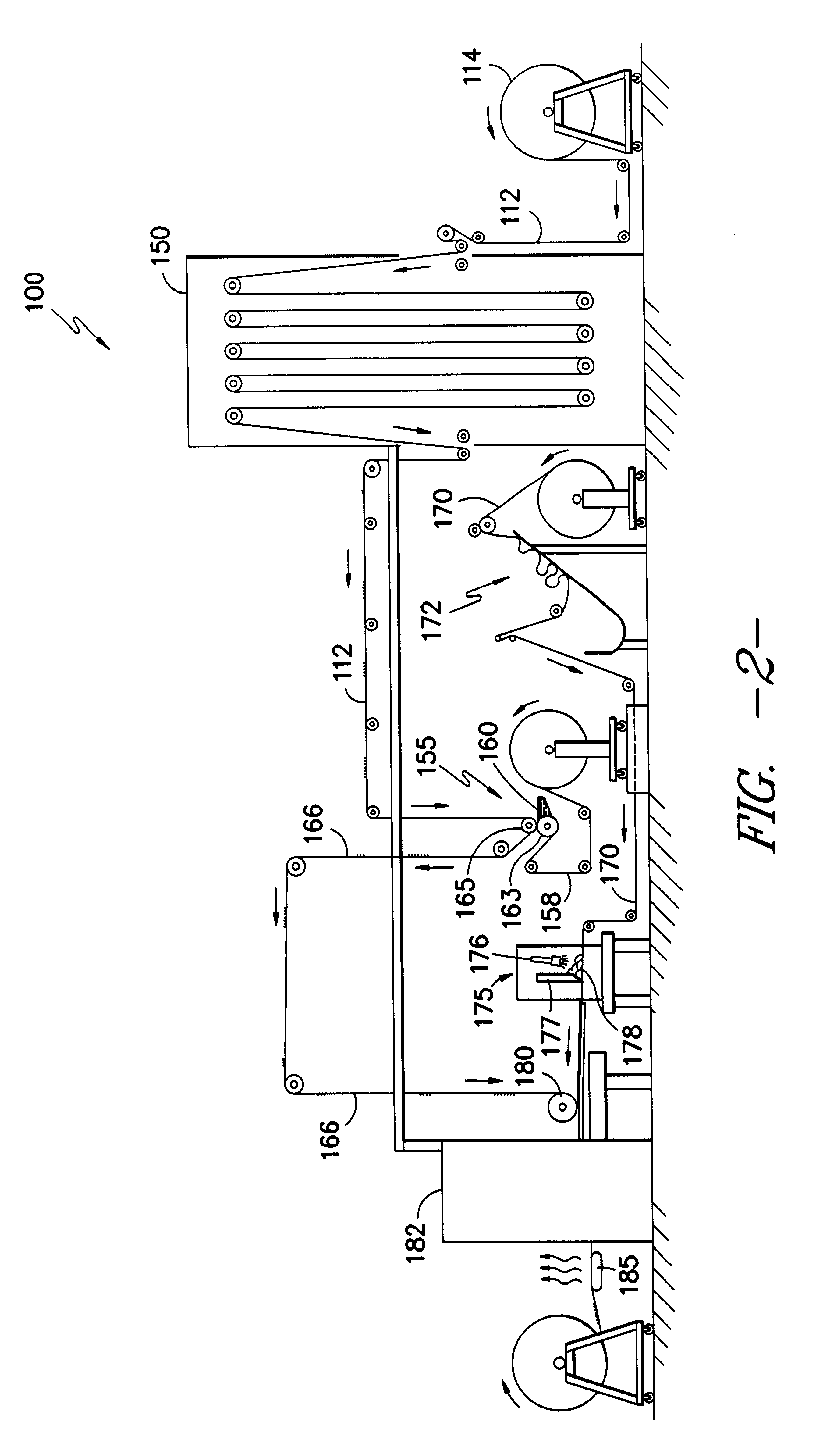
It is still a further related object of the present invention to provide a continuous process for the in-situ formation of a cushioned carpet composite wherein a reinforcement layer is adhered between a primary carpet base and a backing layer through the in-situ application of a polyurethane forming composition without the need for an intermediate adhesion step.
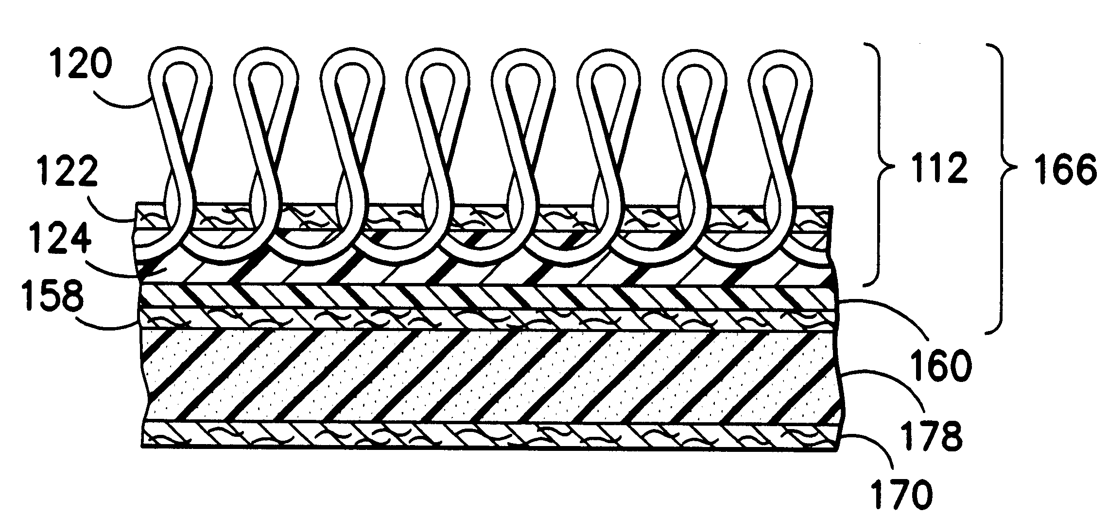
With regard to the presently preferred embodiment, in the tufted carpet of the present invention (FIG. 3A), the primary carpet fabric 112 preferably comprises a loop pile layer 120 of pile-forming yarns tufted into a primary backing 122 as is well known and held in place by a precoat of latex or a hot melt adhesive 124. It is contemplated that the latex or hot melt adhesive may be added in-line after removal from the carpet roll prior to the application of any other adhesive as described below. The carpet may be steamed after addition of the precoat to facilitate subsequent printing operations if desired to reduce stresses.
As indicated, in the preferred practice the polymer application unit 175 applies a deposit of a polymer 178 (FIGS. 3A, 3B) to the backing material 170 after which the height of the polymer is doctored to a desired level. In the preferred practice, the polymer applied is a polyurethane-forming composition based on a so called soft segment prepolymer of MDI (diphenylmethane diisocyanate) or an MDI derivative. The polyurethane-forming composition also preferably incorporates a silicone surfactant to improve both the frothability and stability of the polyurethane layer or "puddle" which is spread across the surface of the backing material 170. As stated in U.S. Pat. No. 4,522,857, suitable equivalents to polyurethane, such as styrene butadiene latex or PVC, can also be used as the polymer.
In an important aspect of the present invention, the primary carpet fabric 112 which is preferably joined to reinforcement material 158 to form the preliminary composite 166 can be laid directly into the polyurethane-forming composition immediately after it is doctored to the appropriate level without any need to significantly heat either the preliminary composite 166 or the polyurethane-forming composition. Accordingly, the preliminary composite 166 and the backing material 170 with the applied polyurethane-forming composition may be simultaneously delivered at room temperature to a mating roll 180 immediately following the application and doctoring of the polyurethane-forming composition. As will be appreciated, this avoidance of lag time between formation of the components of the cushioned carpet composite permits highly efficient processing readily controllable either manually or by computer control means (not shown) as are well known to those of skill in the art. In the preferred process, the preliminary composite 166 may be slightly preheated to improve operating control during lamination and curing but such preheat is not essential to formation of the desired product.
Simultaneously with the passage of polymer through the reinforcement material 358, a backing material 370 such as the nonwoven polyester / polypropylene described above is preferably passed in adjacent mating relation to the polymer-coated reinforcement material 358 between the polymer contact roll 360 and a backing material mating roll 379. A doctor blade 377 serves to control the depth of the polymer which does not pass through the reinforcement material 358 into contact with the backing material 370. Thus, it is to be appreciated that a polymer sandwich structure is formed preferably comprising a layer of backing material 370, a relatively thin layer of polymer 378 such as polyurethane which has been passed through a layer of reinforcement material 358, and a doctored layer of polyurethane 378 which was not passed through the reinforcement material 358. This polymer sandwich structure can thereafter be passed to the mating roll 380 for joinder with the primary carpet fabric 312 by laying the primary carpet fabric 312 directly into the doctored layer of polyurethane 378 without any precuring operation.
Problems solved by technology
Specifically, it has not been previously recognized that a single process could be used to bring all the layers of the cushioned carpet composite together by laying a primary carpet fabric, either with or without some degree of preheat, directly into a mechanically frothed polyurethane-forming composition prior to curing the polyurethane and without an intermediate layer of material.
Method used
View moreImage
Smart ImageViewing Examples

Examples
Embodiment Construction
tufted carpet was produced by the apparatus and process as illustrated and described in relation to FIG. 2. The carpet produced has the configuration illustrated and described in relation to FIG. 3A. The production parameters were as follows:
Login to View More PUM
| Property | Measurement | Unit |
|---|---|---|
| shrinkage | aaaaa | aaaaa |
| thickness | aaaaa | aaaaa |
| thickness | aaaaa | aaaaa |
Abstract
An improved cushioned carpet fabric is provided. The cushioned carpet comprises a primary carpet having a primary base and a plurality of pile-forming yarns projecting outwardly from one side. A layer of reinforcement material is bonded to the primary base on the side opposite the pile forming yarns. The reinforcement layer is adjacent to and embedded in, a cushion layer of a polymer such as a polyurethane. There is preferably no additional adhesive between the cushion layer and the layer of reinforcement material since the primary carpet fabric is mated in-situ to the polyurethane-forming composition without preheating the polyurethane-forming composition. An apparatus and process for forming the cushioned carpet fabric of the present invention are also provided.
Description
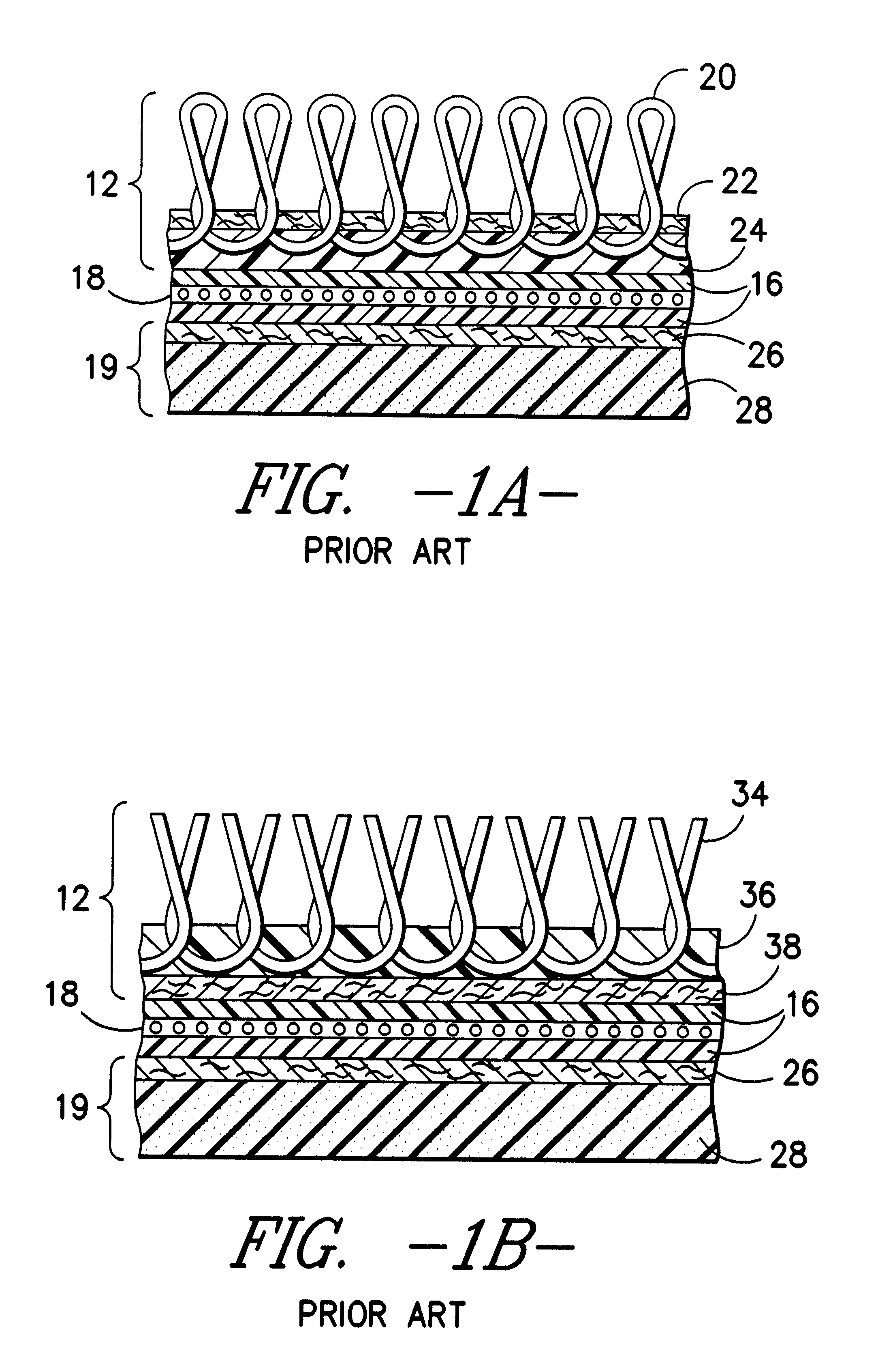
The present invention relates to cushion backed carpet and more particularly to carpet having a polymer backing preferably formed from a polyurethane-forming composition which is mated to a primary carpet fabric in an in-situ manner without pre-curing the polyurethane-forming composition. A process and apparatus for forming the cushion backed carpet of the present invention are also provided.Carpet and carpet tiles having cushioned backings are well known to those of skill in the art. Such cushioned backed carpet is disclosed, for example in my U.S. Pat. No. 4,522,857 (incorporated by reference). An example of a prior art tufted carpet product is illustrated in FIG. 1A and an example of a prior art bonded carpet product is illustrated in FIG. 1B herein.In the prior art tufted carpet, a primary carpet fabric 12 is embedded in an adhesive layer 16 in which is embedded a layer of glass scrim or nonwoven material. A foam base composite 19 is likewise adhesively bonded to the adhesive la...
Claims
Login to View More Application Information
Patent Timeline
 Patent Type & AuthorityPatents(United States)
IPC IPC(8): D06N7/00D06N3/12D06N3/14A47G27/02A47G27/00A47L23/22B32B5/24B32B27/40C08L75/00D05C17/02D06M17/00
CPCD06N3/14D06N7/0086D06N7/0073D06N7/0081D06N7/0078D06N7/0068D06N2201/0254D06N2201/0263Y10T156/1084D06N2203/068D06N2205/20D06N2205/06D06N2203/066D06N2201/02Y10T428/23979Y10T428/23986Y10T428/23993B32B3/16B32B5/18B32B37/12C09J5/06
InventorHIGGINS, KENNETH B.
OwnerMILLIKEN & CO