Method and device for sealing a tap hole in metallurgical containers

a technology for metallurgical containers and tap holes, which is applied in the direction of manufacturing converters, furnaces, charge manipulation, etc., can solve the problems of inability to avoid optimal filling of the opening with sand in the manual filling process, time-consuming and labor-intensive, and inability to achieve optimal filling of the opening with sand

Inactive Publication Date: 2002-10-29
SMS DEMAG AG
View PDF9 Cites 18 Cited by
  • Summary
  • Abstract
  • Description
  • Claims
  • Application Information

AI Technical Summary

Problems solved by technology

In this connection, it cannot be avoided that slag flows partially with the stream of the molten mass out of the tap hole.
An optimal filling of the opening with sand is not possible for a manual filling process.
Moreover, this step, in the case that cleaning work has to be carried out, is time-consuming and labor-intensive.
Moreover, the slag-poor tapping system for a converter is known in connection with a float or slag stopper.
A disadvantage is, however, that the sealing of the tap opening depends only on the lowered molten mass / slag interface and cannot be influenced otherwise.
Moreover, a completely slag-free outflowing of the molten mass is not possible with this float solution.
A slag-free tapping is not possible by this solution because the sensor reacts only after a portion of the slag has already flown through the opening.
However, this entails a great splashing risk.
In all of the aforementioned tapping methods of the prior art only a slag-poor, but not a slag-free, tapping is possible.
The oxygen contents of the FeO in the slag makes the desulfurization and degassing more difficult.
Accordingly, problems during opening of the tap hole are circumvented.
As a result of the movement of the introduction means, the plug is displaced, the sleeve at the bottom is destroyed, and the filler material exits.

Method used


Image

  • Method and device for sealing a tap hole in metallurgical containers
  • Method and device for sealing a tap hole in metallurgical containers
  • Method and device for sealing a tap hole in metallurgical containers

Examples


Embodiment Construction

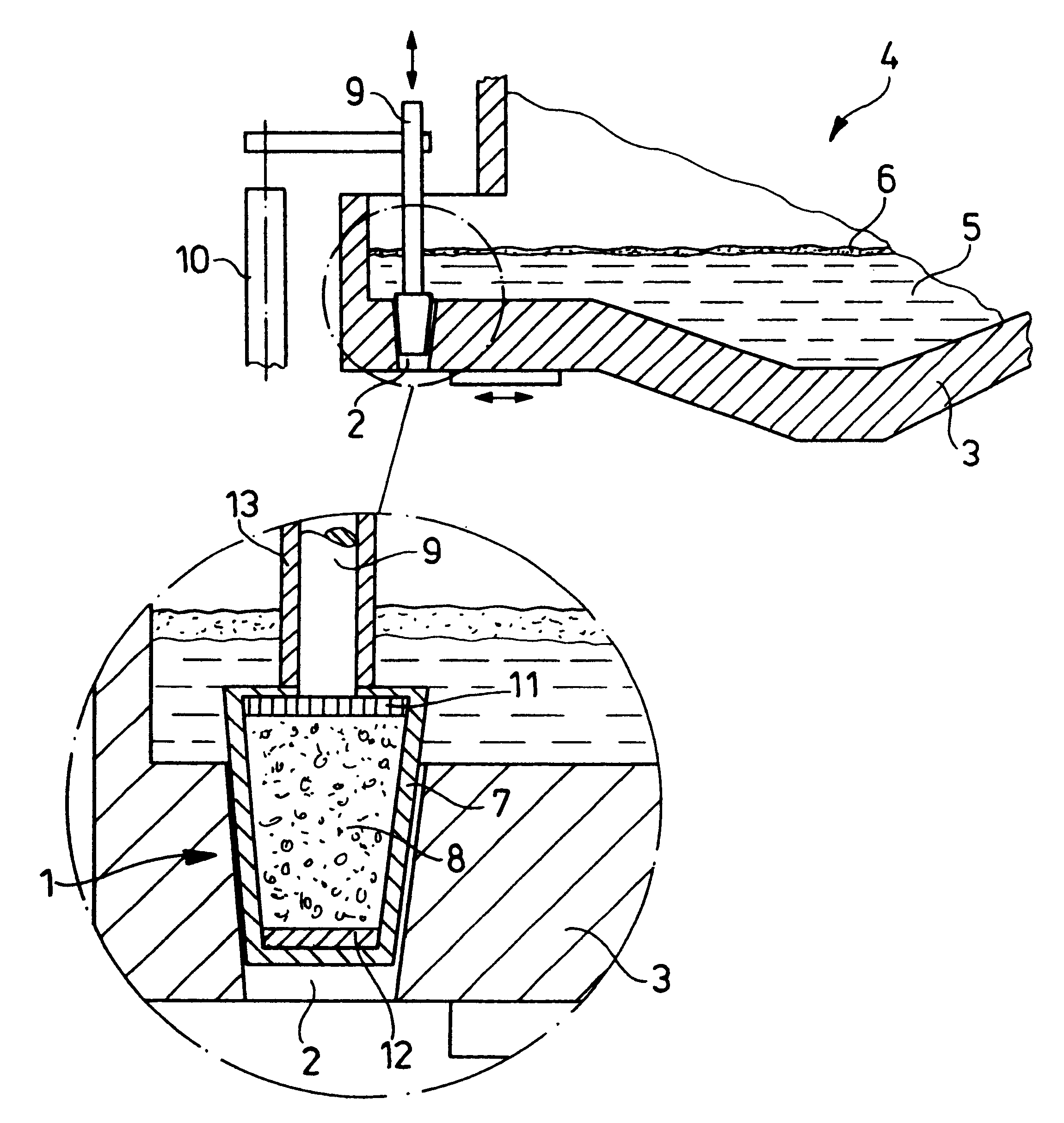
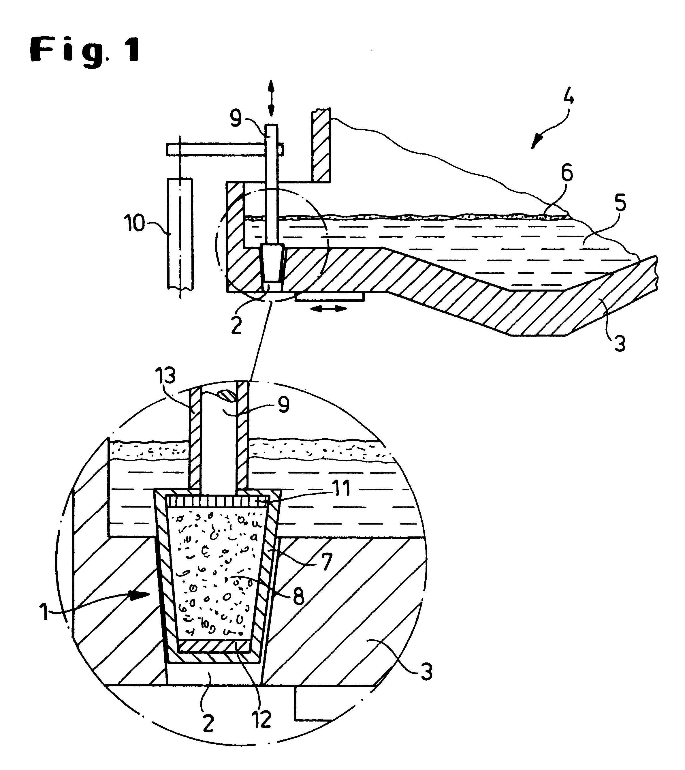
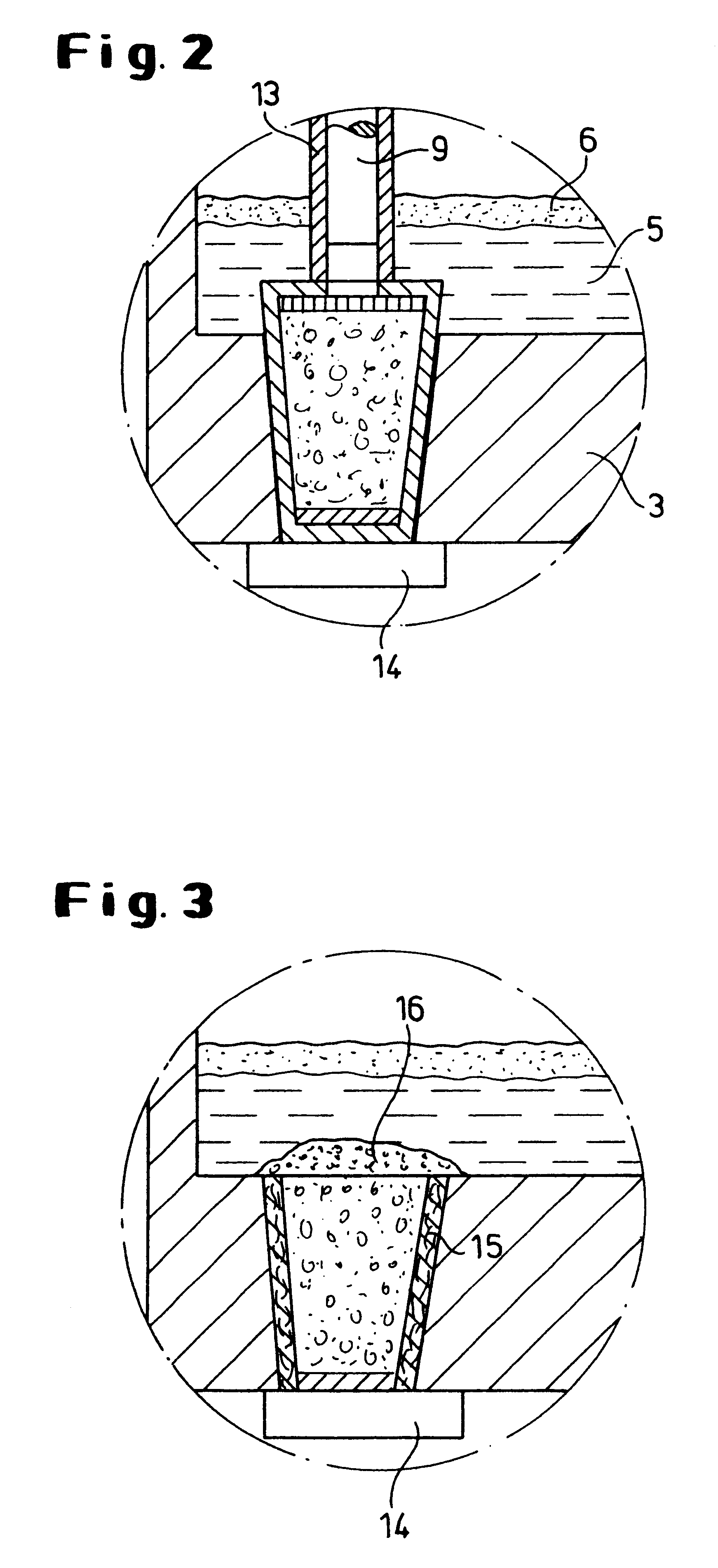
FIG. 1 shows in a partial enlargement the plug 1 of the tapping system during the immersion process into the tap opening 2 at the container bottom 3 of an furnace 4. Reference numeral 5 indicates the molten mass of steel, reference numeral 6 the lighter slag.

The plug 1 comprises a sleeve 7 as well as a core 8 of filler sand which is surrounded by the sleeve 7 acting as a protective jacket.

In this embodiment, the plug 1 is introduced, coming from the interior of the container, by means of a metal rod 9 into the tap opening 2 via a lifting system 10.

The metal rod 9 acts via a support grate 11 onto the filler sand 8. The plug 12 forms the closure of the filler sand core 8 relative to the bottom area of the plug sleeve. The diameter of the plug corresponds at least approximately to the diameter of the tap opening 2 at its lower end.

The metal rod 9 is enclosed by a protective pipe 13 for a temporary protection thereof. It can be formed with the sleeve 7 of the plug as a unitary part or c...


PUM

PropertyMeasurementUnit
timeaaaaaaaaaa
temperatureaaaaaaaaaa
weightaaaaaaaaaa

Abstract

In a method for sealing a tap opening in a metallurgical container a plug with a plug sleeve and a refractory flowable material is provided having a metal rod or pipe surrounded by a protective pipe connected thereto. The plug sleeve and the protective pipe are made of a material resistant to a molten mass of metal in the metallurgical container only for a short period of time. The material is a temporarily heat-insulating material which cokes within the molten mass of metal and is cardboard or wood. The time of introduction of the plug sleeve is controlled based on measured parameters of the molten mass. The plug is introduced into the tap opening by guiding the plug with the metal rod or pipe through the molten mass in the metallurgical container. The plug sleeve changes by temperature action of the molten mass of metal such that the flowable material is distributed in the tap opening and seals the tap opening. The tap opening is then closed from the exterior of the metallurgical container and the plug sleeve in the tap opening as well as the protective pipe are coked and destroyed.

Description

1. Field of the InventionThe invention relates to a method and a device for sealing a tap hole in metallurgical containers.2. Description of the Related ArtThe invention relates to a method and a device for sealing a tap hole in metallurgical containers.Recently, there has been a tendency to produce steels of a high degree of purity, so-called clean steel, in order to thus fulfill the increasing requirements for improved steel properties. The separation of molten mass and slag in the electric furnace or converter with subsequent secondary metallurgy is an essential influencing factor with respect to the degree of purity.From the prior art several tapping systems are known. In a conventional electric arc furnace tapping is carried out, for example, by lateral tilting of the furnace vessel. The furnace is tilted toward the tapping side for tapping, and the outflow of the molten mass is terminated by a fast return tilting after reaching the desired tapping weight. In this connection, i...

Claims


Application Information

Patent Timeline
Patent Type & Authority Patents(United States)
IPC IPC(8): B22D41/46B22D41/14C21C5/46B22D2/00F27D3/14
CPCB22D41/46C21C5/4653F27D3/1536F27D3/159
Inventor PLESCHIUTSCHNIGG, FRITZ-PETERWU, WEI-PING
Owner SMS DEMAG AG
Why Eureka
Try Eureka