
Switching amplifier incorporating return-to-zero quaternary power switch

a technology of quaternary power switch and switching amplifier, which is applied in the direction of amplifiers, dc amplifiers with modulator-demodulator, semiconductor devices/discharge tubes, etc., can solve the problems of h-bridge, h-bridge is typically used, and the integration level is not optimal

Inactive Publication Date: 2002-10-29
RALPH CHANG JONG
View PDF2 Cites 33 Cited by
  • Summary
  • Abstract
  • Description
  • Claims
  • Application Information

AI Technical Summary

Problems solved by technology

This correspondingly also results in distortion in the output circuit.
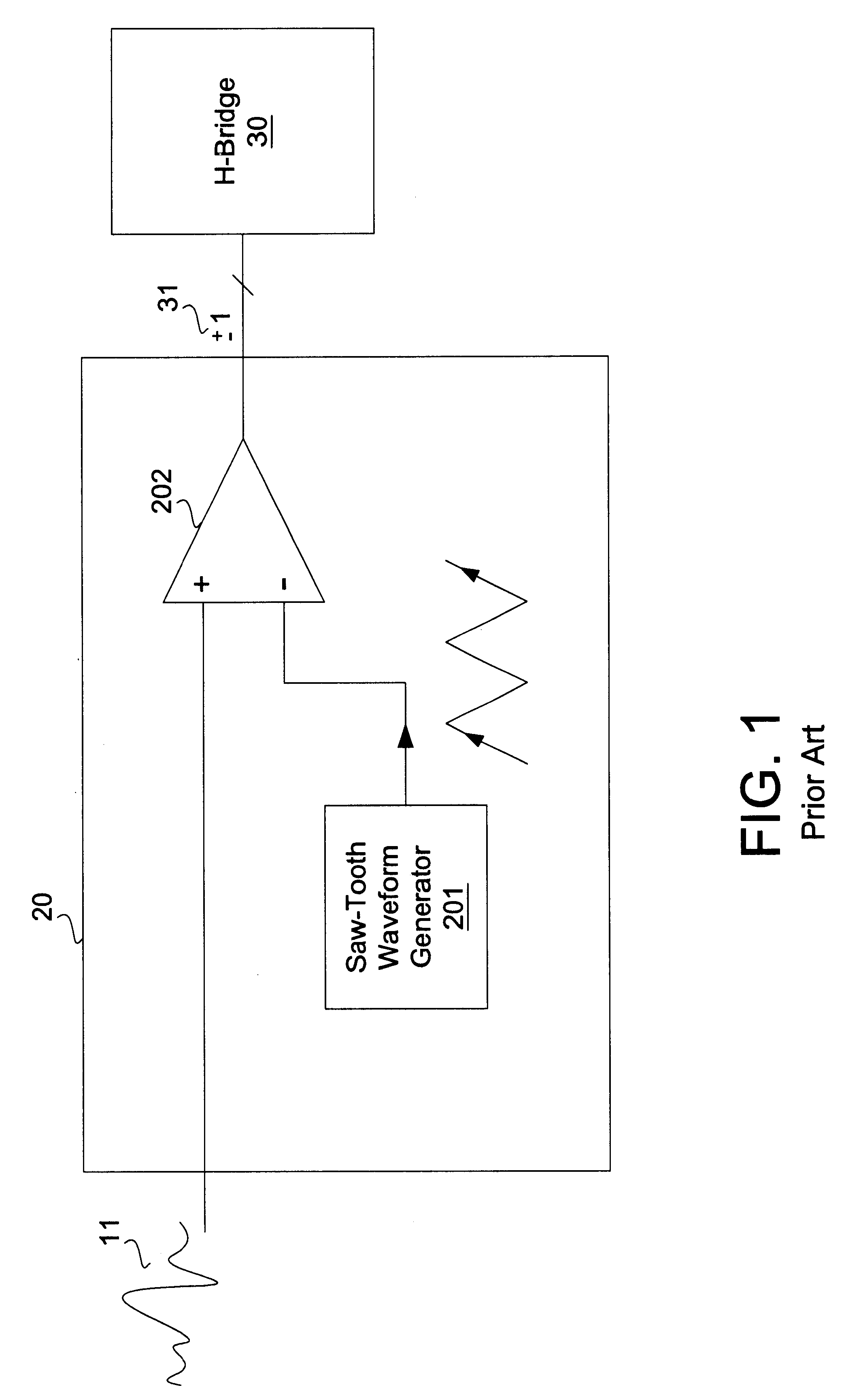
An apparent drawback for this type of Class-D amplifier is that while the control circuit 20 in FIG. 1 can be implemented in CMOS, the H-bridge is typically outside the controller circuit.
The integration level is not optimum and hence the cost is higher than a single integrated CMOS Class-D amplifier."
Both the traditional saw-tooth and binary sigma-delta modulation provide poor power efficiency due to their frequent switching even when there are little or no input signals.
Another problem is caused by the binary nature of the output state and finite turn-on resistance associated with the transistors of the H-bridge is that there will always be power consumed by these transistors regardless of the shape or amplitude of the input signal.
Thus, because of these binary states, power consumption is always present even if there is no input signal to amplify.
While the ternary power switch amplifier can achieve higher power efficiency than binary power switch amplifiers, there is significant harmonic distortion caused by the error caused by the error voltages associated with the output transistors as explained below:"
Thus, the error associated with the turn-off time of a transistor is much shorter than that associated with the turn-on time of a transistor.
Accordingly, due to this mismatch, the ternary switching sequence introduces substantial harmonic distortion at the output.
Since the rise time and fall time of switches BH and BL do not typically match, the harmonic distortion is increased from the switching operation.
As explained earlier, transistors BL and BH do not match, and hence there is a residual error voltage associated with this transition.

Method used


Image

  • Switching amplifier incorporating return-to-zero quaternary power switch
  • Switching amplifier incorporating return-to-zero quaternary power switch
  • Switching amplifier incorporating return-to-zero quaternary power switch

Examples


Embodiment Construction

)

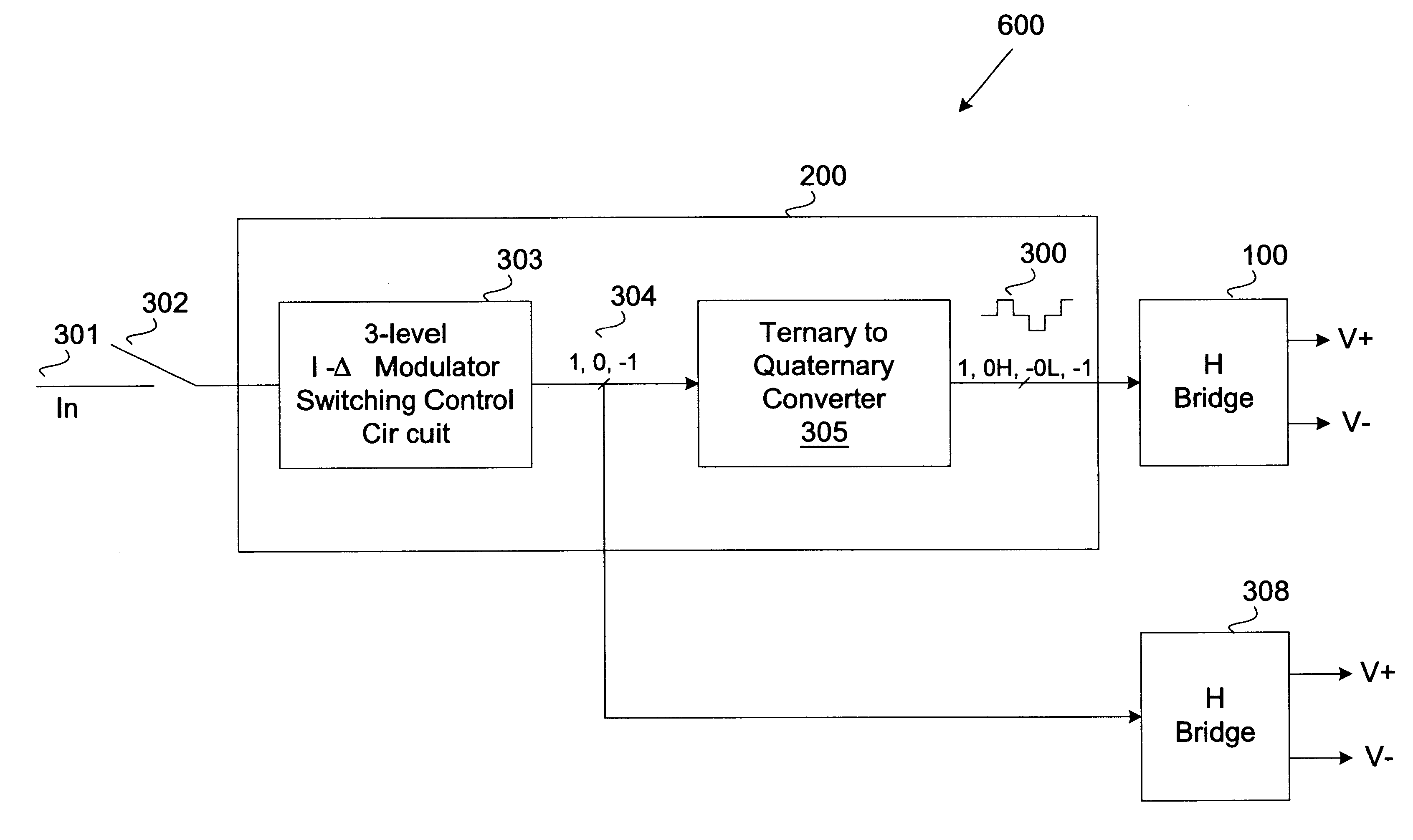
An improved switching amplifier incorporating return-to-zero quaternary power switch 600 as illustrated in FIG. 6 comprises a switch control circuit 200 and an H-bridge circuit 100 implementing quaternary switch control signal 300 in accordance with the principles of this invention. Switch control circuit 200 produces a quaternary output signal 300 comprising four states (+1, 0H, -1, and 0L ), otherwise referred herein as "quaternary states", as will later be explained in further detail. Quaternary state signal 300 is used to control the output H-bridge 100. Switch control circuit 200 can comprise a digital circuit if its input signal 301 comprises a digital waveform, or an analog and digital circuit combination if input 301 is an analog waveform. The operational principle of this invention remains the same in both cases. If switch control input signal 301 is an analog signal waveform, switching amplifier 100, also referred to herein as an H-bridge circuit comprises a traditional C...


PUM


Abstract

Invention resides in a switching amplifier having a quaternary input control signal that provides quaternary levels (1, 0H, -1, and 0L) which is coupled to an H-bridge amplifier to provide error cancellation in switching amplifier output signal. The quaternary control signal alternates from a zero state at a high level ("0H") to a zero state at a low level ("0L") between each non-zero state (+1 or -1). In a preferred embodiment, a three-level sigma-delta modulator is provided for greater operational efficiency for ease of detecting zero states and minimizing power. The three-level sigma-delta modulator receives and converts an amplifier input signal into a ternary output signal that is then coupled to a ternary-to-quaternary converter to generate the quaternary control signal to provide as input to the H-bridge.

Description

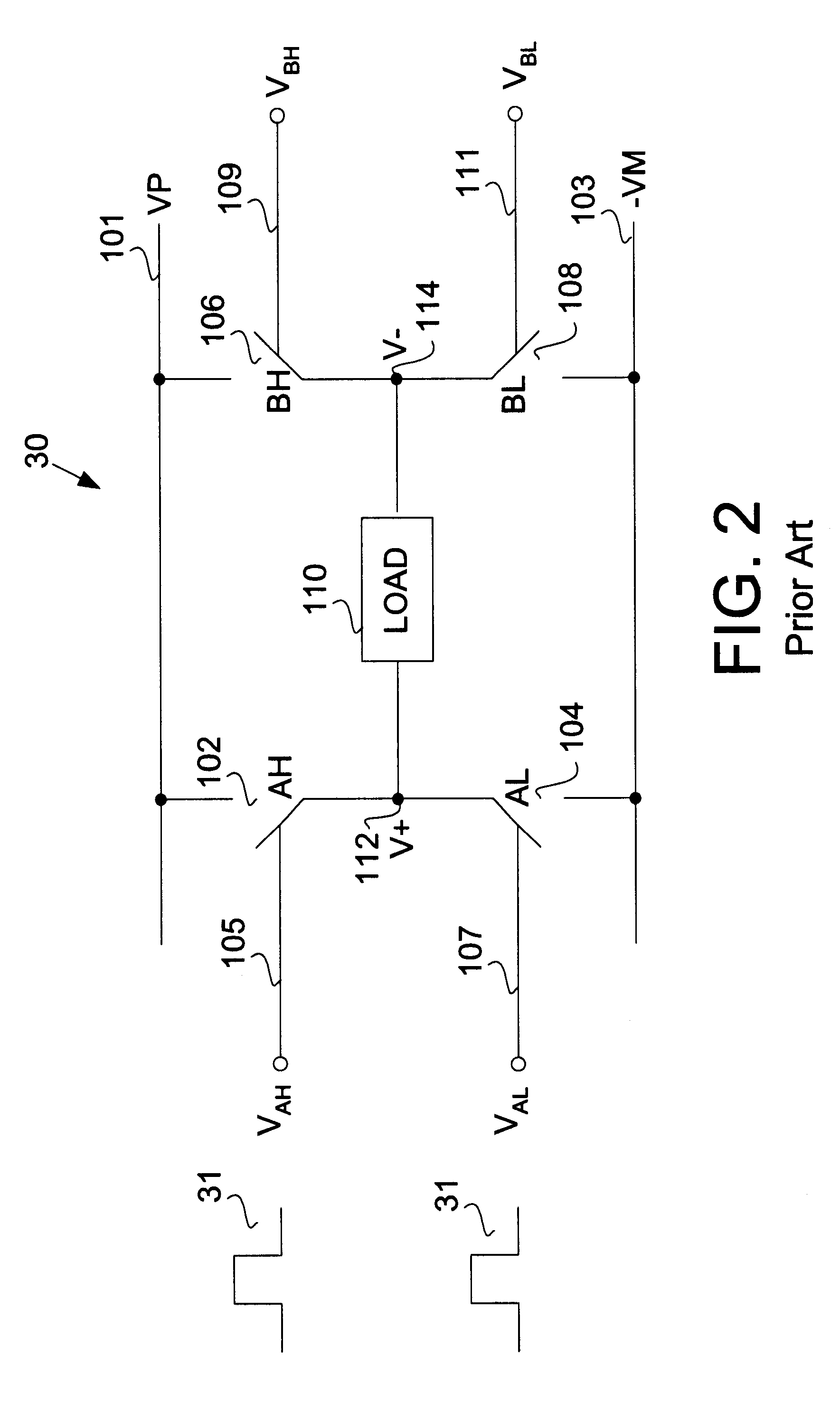
Invention relates to amplifier circuits, and more particularly to switching amplifier power switch.BACKGROUND OF INVENTION"Typical Class-D amplifier such as that of Texas Instrument (TI) Cass D Stereo Audio Power Amplifier described in TI TPA005D02 Class D Stereo Audio Power Amplifier Evaluation Module User's Guide comprises an analog input and an analog output. A simplified Class-D amplifier is illustrated in FIG. 1. The amplifier constitutes two parts: the control circuit 20 and the H-bridge 30. The control circuit 20 consists of a saw-tooth waveform generator 201 and a comparator 202. The analog input 11 is compared with the saw-tooth waveform to produce a binary digital output 31. The binary digital output is then used to control the ON / OFF of an output power stage such as an H-bridge circuit 30. As shown in greater detail in FIG. 2, H-bridge circuit 30 comprises two pairs of switches, a first pair of switches: switch 102 (AH) and switch 104 (AL), and a second pair of switches: ...

Claims


Application Information

Patent Timeline
Patent Type & Authority Patents(United States)
IPC IPC(8): H03F3/217H03F3/20
CPCH03F3/2173H03F2200/331
Inventor HSU, WEI-CHAN
Owner RALPH CHANG JONG
Learn More