
Method of making nitrided active elements

a technology of active elements and nitride, which is applied in the field of making nitrided active elements, can solve the problems of low resistivity value, poor high frequency application suitability, and poor wear resistance of the pole, and achieve the effect of increasing wear resistance and/or resistivity

Inactive Publication Date: 2002-11-05
ORACLE INT CORP
View PDF34 Cites 20 Cited by
  • Summary
  • Abstract
  • Description
  • Claims
  • Application Information

AI Technical Summary

Benefits of technology

The invention overcomes the shortcomings of the prior art by providing improved active elements for use with magnetic heads and a method of manufacturing the active elements, wherein the active elements are hardened to increase wear resistance and / or resistivity.
Preferably, depositing a magnetic material comprises depositing nickel-iron alloy. Furthermore, nitriding the magnetic member preferably includes plasma nitriding the magnetic member. Advantageously, plasma nitriding the magnetic member may be performed at a temperature below 300 degrees Celsius to avoid adverse effects on organic components of the active element.

Problems solved by technology

While electroplating provides good dimensional control, the resultant poles suffer from at least two problems.
First, such poles have low resistivity values, and, thus, are not well suited for high frequency applications.
Second, the poles are relatively soft, which results in increased pole tip recession.
Consequently, it is difficult to achieve precise dimensional control.
With such a construction, it is difficult to achieve precise dimensional control.
While nickel-iron alloys provide good shielding properties, these materials wear excessively and, therefore, limit head life.

Method used


Image

  • Method of making nitrided active elements
  • Method of making nitrided active elements
  • Method of making nitrided active elements

Examples


Embodiment Construction

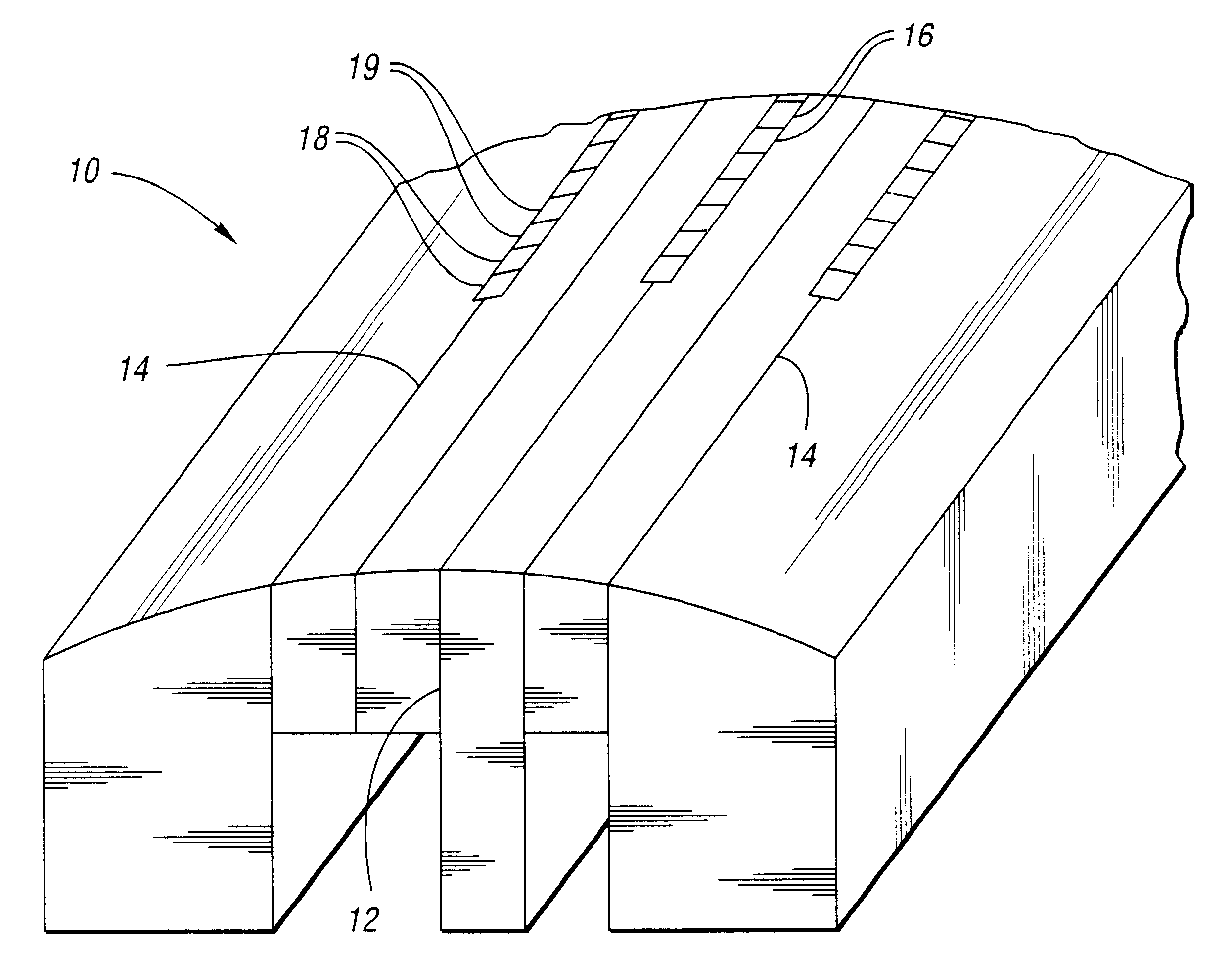
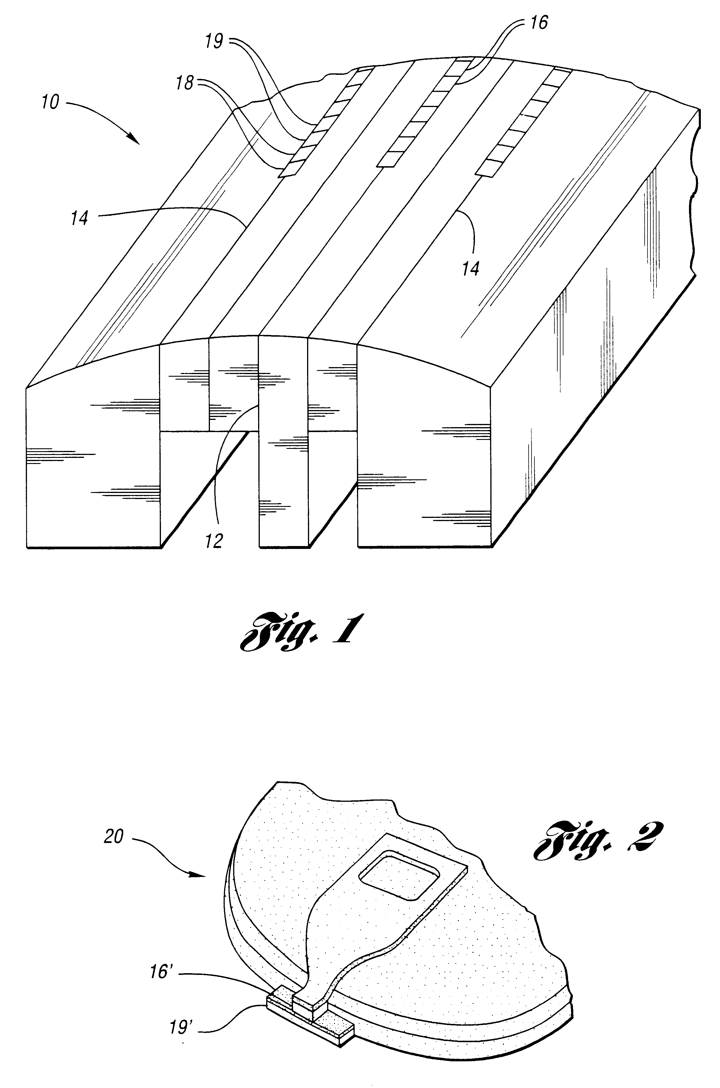
FIG. 1 shows a magnetic tape head 10 according to the invention having a plurality of magnetic gaps, such as a write gap 12 and read gaps 14. The write gap 12 has a plurality of active elements, such as write or recording elements 16, disposed therein. Each of the read gaps 14 also has a plurality of active elements, such as servo elements 18 and read elements 19, disposed therein.

FIG. 2 shows a magnetic disk head 20 according to the invention. The disk head includes a write element 16', which is similar to the write element 16, and a read element 19', which is similar to the read element 19. As used herein, the term magnetic head may refer to either or both of the tape head 10 and the disk head 20.

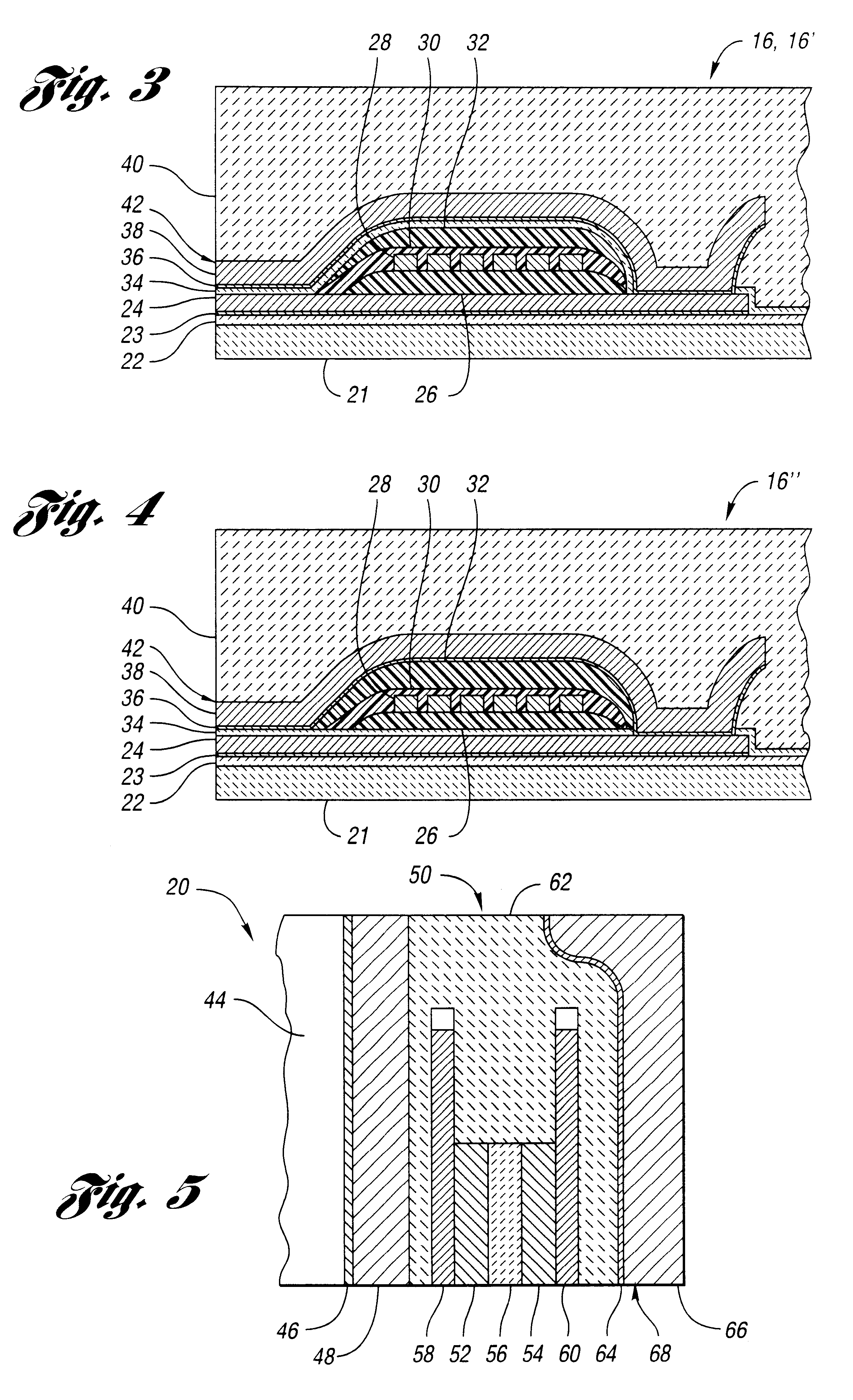
With reference to FIG. 3, a method of manufacturing recording elements 16 and 16' will now be described. As shown in FIG. 3, each recording element 16 and 16' includes a substrate 21 made of any suitable material, such as aluminum oxide titanium carbide, ferrite, aluminum oxide, or silico...


PUM

PropertyMeasurementUnit
temperatureaaaaaaaaaa
thicknessaaaaaaaaaa
thicknessaaaaaaaaaa

Abstract

A method of manufacturing an active element for use with a magnetic head includes depositing a magnetic material to form a magnetic member, and nitriding the magnetic member after the depositing step. Preferably, the depositing step comprises depositing nickel-iron alloy, and the nitriding step comprises plasma nitriding the magnetic member. Advantageously, plasma nitriding may be performed at a temperature below 300 degrees Celsius to avoid adverse effects to components of the active element, such as organic planars. Active elements manufactured according to the method of the invention are also disclosed.

Description

The invention relates to active elements for use with magnetic heads and a method of manufacturing the elements, wherein the elements include nitrided magnetic members.An important and continuing goal in the data storage industry is that of increasing the density of data stored on a medium. For tape storage systems, this goal has lead to decreasing track width in magnetic tapes, and increasing track density in magnetic tape heads. Similarly, for disk storage systems, this goal has lead to decreasing track width in magnetic disks, and increasing track density in magnetic disk heads. As track density in tape and disk heads increases, so does the need for precise processing and critical dimension control of recording elements and / or read elements disposed in the tape and disk heads.Prior recording elements include magnetic poles that comprise nickel-iron alloys, such as permalloy, and are made using electroplating manufacturing methods. While electroplating provides good dimensional co...

Claims


Application Information

Patent Timeline
Patent Type & Authority Patents(United States)
IPC IPC(8): G11B5/255G11B5/10G11B5/39G11B5/31G11B5/11H01F41/20
CPCG11B5/10G11B5/255G11B5/3106G11B5/3903G11B5/3967G11B5/11Y10T29/49044G11B5/3109G11B5/3163G11B5/3954Y10T29/49021Y10T29/49032Y10T29/49043Y10T29/49034Y10T29/49046Y10T29/49041
Inventor SCHWARTZ, BRADFORD C.HERRERA, STEVEN C.
Owner ORACLE INT CORP
Learn More