Low-E matchable coated articles and methods of making same

a coating and low-e technology, applied in the field of low-e matchable coated articles and methods of making same, can solve the problems of low-e coating system, insufficient color matchability of 455 patents, and less than desirable solar control characteristics, etc., and achieve good color stability.

Inactive Publication Date: 2002-11-05
GUARDIAN GLASS LLC
View PDF69 Cites 109 Cited by
  • Summary
  • Abstract
  • Description
  • Claims
  • Application Information

AI Technical Summary

Benefits of technology

An object of this invention is to provide a low-E coating o...

Problems solved by technology

While the coating systems of the '585 patent are excellent for their intended purposes, they suffer from certain disadvantages.
This enables high transmission and low-E characteristics, but less than desirable solar control (e.g., shading coefficient) characteristics.
Thus, the low-E coating system of the '455 patent is unfortunately not sufficiently color matchable after heat treatment with its non-heat treated counterpart, and lacks superior solar control characteristics such as shad...

Method used


Image

  • Low-E matchable coated articles and methods of making same
  • Low-E matchable coated articles and methods of making same

Examples


examples 1-4

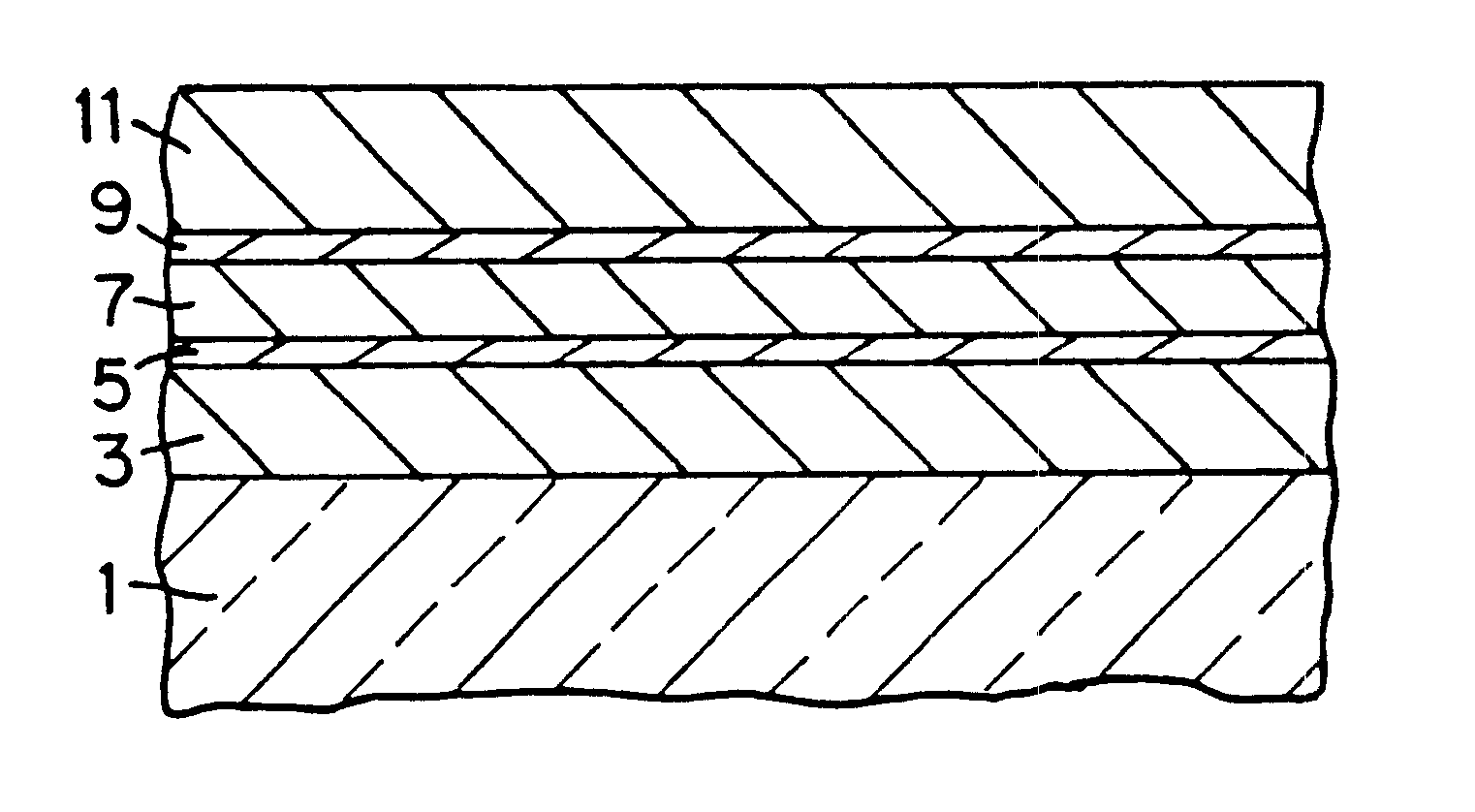
The following four Example coated articles (each annealed and heat treated) were made in accordance with certain embodiments of this invention. For each of the four Examples, the layer system was: glass / Si.sub.3 N.sub.4 / NiCr / Ag / NiCr / Si.sub.3 N.sub.4 (e.g., see FIG. 1). For each of these Examples, the substrate was of substantially clear 5.6-6.0 mm thick soda-lime-silica glass. The coater / process setups for the four Examples were as follows.

With regard to Examples 1-2, they were made using a G-49 large area flat glass sputter coater produced by Airco, Inc., using line speed of 170 IPM, with coat zones 3-5 being used; where "*" means Al content of approximately 10% and gas (e.g., Ar, N.sub.2) flow was measured in sccm units. All targets for Examples 1-2 were C-Mag targets, except that the targets used for depositing the Ag and NiCr layers (target #s 19-21) were planar. Moreover, in Examples 1-2 the first silicon nitride layer was deposited in coat zone 3 using AC power, the NiCr and ...

examples 3-4

were made using a Leybold TG-1 sputter coater using line speed of 4 m / min.; where "*" again means aluminum (Al) target content of approximately 10% and gas (e.g., Ar, N.sub.2) flow was measured in sccm units. Target #s 34, 42, 55 and 61 were 2.times.C-Mag targets, target #s 44, 51 and 53 were planar targets, and target #65 was a Twin-Mag target. Pressure was measured in mTorr. The coater was set up and ran as follows during the sputtering of

TABLE 5 Coater Setup / processes for Examples 3-4 Power Voltage Freq. Cathode Target (kW) (V) Pressure Ar flow N.sub.2 flow (kHz) EXAM- PLE #3 #34 Si / Al* 64.5 395 3.6 203 452 28.1 #42 Si / Al* 64.5 341 3.1 200 452 28.7 #44 NiCr 12.5 385 2.5 220 0 DC #51 Ag 4.55 466 2.3 315 0 DC #53 NiCr 12.5 421 2.4 220 0 DC #55 Si / Al* 62 373 3.5 200 447 27.8 #61 Si / Al* 64 374 4.5 200 447 28.1 #65 Si / Al* 62 326 3.5 200 377 27.8 EXAM- PLE #4 #34 Si / Al* 64.5 395 3.6 203 452 28.1 #42 Si / Al* 64.5 341 3.1 200 452 28.7 #44 NiCr 19 347 2.5 220 0 DC #51 Ag 4.55 466 2.3 315 0...


PUM

PropertyMeasurementUnit
Fractionaaaaaaaaaa
Fractionaaaaaaaaaa
Transmittivityaaaaaaaaaa

Abstract

A heat treatable coated article including an infrared (IR) reflecting layer (e.g., of or including Ag), the coated article being able to attain a .DELTA.E* (glass side) no greater than about 3.0, more preferably no greater than 2.5, and even more preferably no greater than 2.0, following or due to heat treatment (e.g., thermal tempering). Accordingly, low-E (i.e., low emissivity) coated articles of certain embodiments of this invention appear from the glass side thereof visually similar to the naked eye both before and after heat treatment. Coated articles herein may be used in the context of insulating glass (IG) window units, vehicle windshields, or any other suitable applications. In certain embodiments of this invention, an exemplary layer stack includes: glass/Si.sub.3 N.sub.4 /NiCr/Ag/NiCr/Si.sub.3 N.sub.4. Other materials may instead be used without departing from the scope and/or spirit of the instant invention which is a low-E matchable product.

Description

This invention relates to low-E coated articles that have approximately the same color characteristics as viewed by the naked eye both before and after heat treatment (e.g., thermal tempering), and corresponding methods. Such coated articles may be used in insulating glass (IG) units, windshields, and other suitable applications.BACKGROUND OF THE INVENTIONSolar control coating systems are known. For example, commonly owned U.S. Pat. No. 5,688,585 discloses a solar control coated article including: glass / Si.sub.3 N.sub.4 / NiCr / Si.sub.3 N.sub.4. One object of the '585 patent is to provide a sputter coated layer system that after heat treatment is matchable colorwise with its non-heat treated counterpart. While the coating systems of the '585 patent are excellent for their intended purposes, they suffer from certain disadvantages. In particular, they tend to have rather high emissivity values (e.g., because no silver (Ag) layer is disclosed in the '585 patent).Low-emissivity (low-E) co...

Claims


Application Information

Patent Timeline
IPC IPC(8): B32B17/10B32B17/06C03C17/36C03C27/06C03C27/12
CPCB32B17/10174C03C17/36C03C17/3618C03C17/3626C03C17/3644C03C17/3652C03C17/3681C03C17/366Y10T428/12944C03C2217/78Y10T428/265Y10T428/12542Y10T428/12896Y10T428/12576
Inventor STACHOWIAK, GRZEGORZ
Owner GUARDIAN GLASS LLC
Why Eureka
Try Eureka