Phase detector with adjustable set point

a technology of phase detector and set point, which is applied in the direction of angle demodulation, automatic control of pulses, transmission, etc., can solve the problems of incorrect interpretation of signals, associated hardware costs, and degraded digital signals, so as to improve overall performance, reduce power consumption, and improve performance.

Inactive Publication Date: 2002-11-19
NORTEL NETWORKS LTD
View PDF6 Cites 34 Cited by
  • Summary
  • Abstract
  • Description
  • Claims
  • Application Information

AI Technical Summary

Benefits of technology

Advantageously, the delay elements are arranged to act on regenerated digital signal pulses. The height and speed of such pulses are more predictable than those of the unregenerated data signal, and consequently the delay circuits work better.
Advantageously, the circuitry in the data and clock paths leading to the phase detector is minimised, thereby reducing power consumption, crosstalk, and improving overall performance.
Advantageously, the phase difference and reference signal pulses can be made to overlap whereby to reduce the data content to be filtered out of the error signal, thereby improving performance.

Problems solved by technology

In the course of transmission of digital signals from a transmitter to a receiver, the digital signals tend to become degraded.
It is also desirable to ensure that the data signal is not sampled near the degraded edges of the received data pulses which would lead to incorrect interpretation of the signal.
This has the disadvantage that it requires the delay circuitry to operate at the full speed of the clock or data signal, with associated hardware costs, power consumption, and crosstalk which can act to degrade the data or clock signal before it reaches the decision circuit and / or phase detector.
This has the disadvantages of being susceptible to pattern-dependent jitter, and operating only over a limited phase range.

Method used


Image

  • Phase detector with adjustable set point
  • Phase detector with adjustable set point
  • Phase detector with adjustable set point

Examples


Embodiment Construction

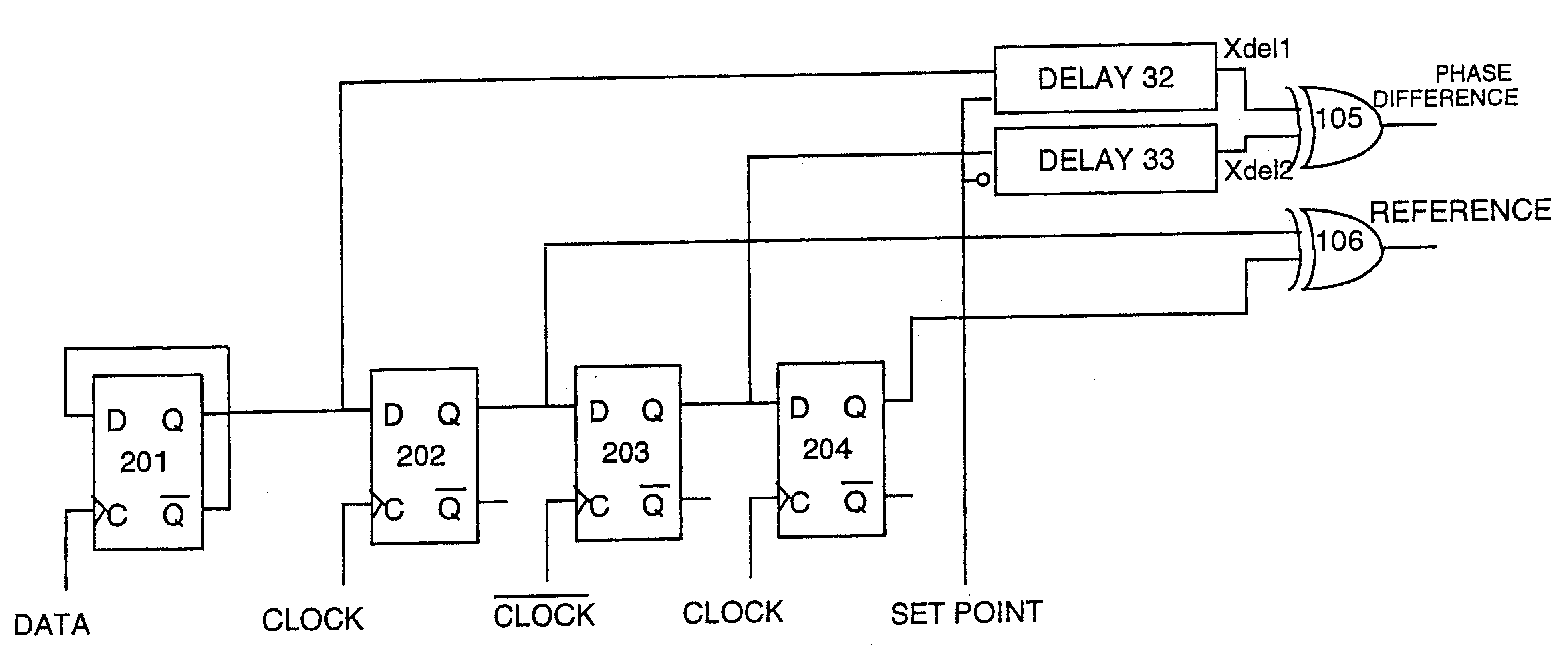
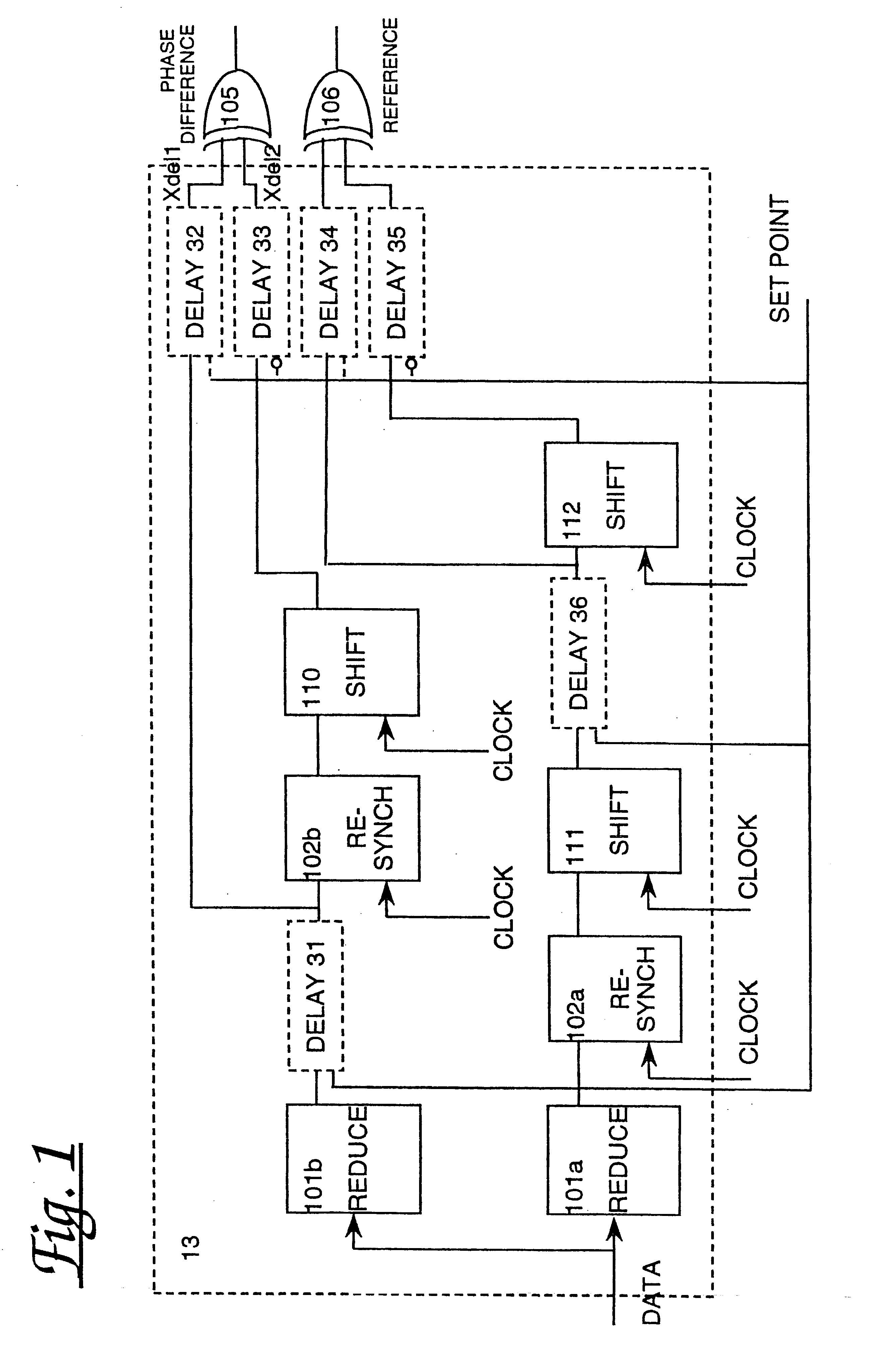
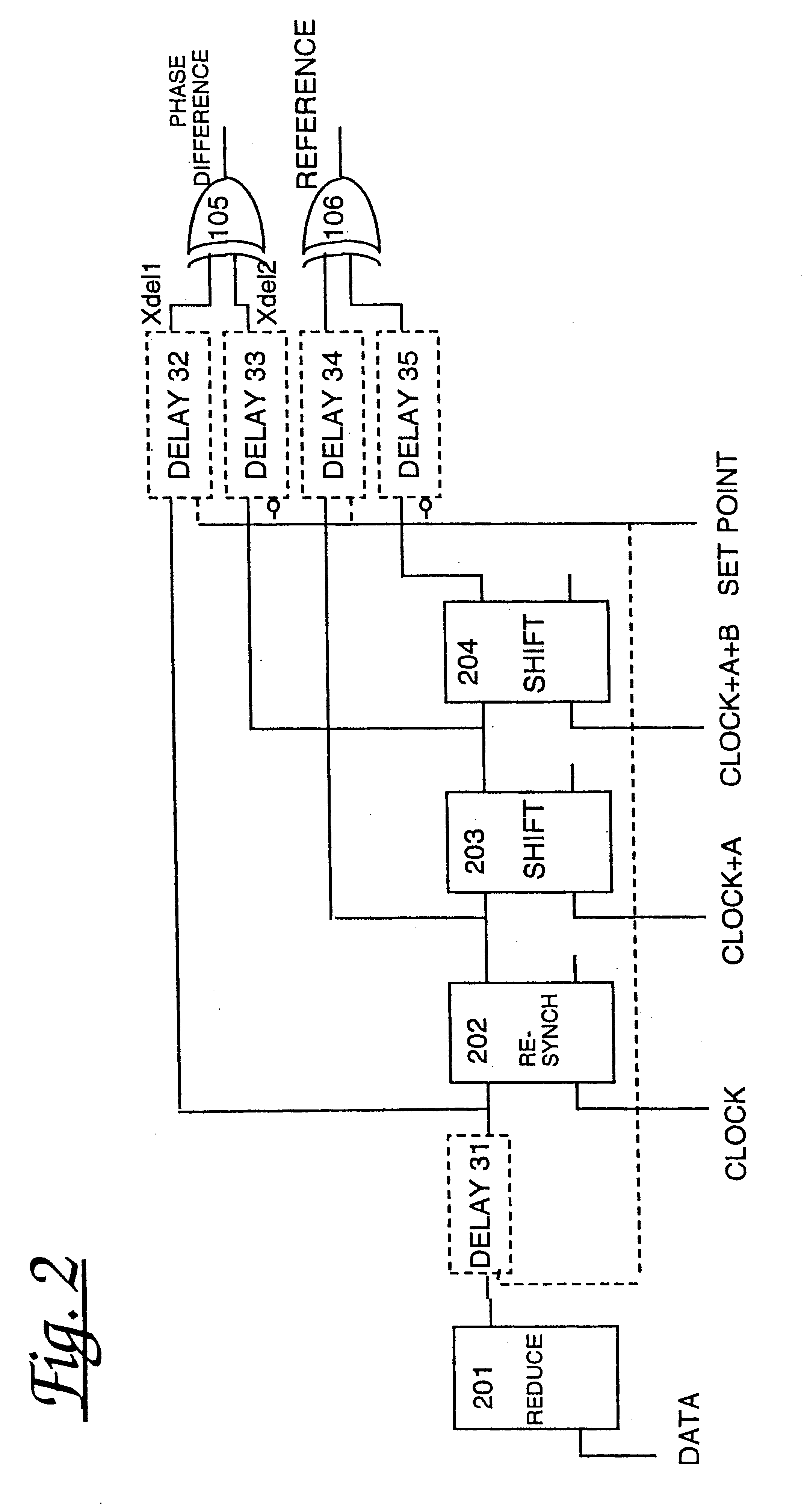
A circuit diagram of a first embodiment of a phase detector 13 in accordance with the present invention is shown in FIG. 1 comprising: first and second data reduction circuits 101a and 101b, first and second resynchronisation circuits 102a and 102b, first, second and third shift register circuits 111, 110 and 112, the first, second, third, fourth, fifth and sixth settable delays 31-36, and first and second Exclusive OR (XOR) gates 105, 106. At least one, but not necessarily all of the settable delays 31-36 must be present.

The first data reduction circuit 101a takes as input a data signal. The first resynchronisation circuit 102a takes as input the output from the first data reduction circuit 101a and a clock signal. The first shift register circuit 111 takes as input the output from the first resynchronisation circuit 102a and a clock signal phase shifted by an amount A. The third shift register circuit 112 takes as input the output from the first shift register circuit 111 (via set...


PUM


Abstract

A digital signal phase detector comprising a first circuit arranged to provide a phase difference signal representative of both the clock period of a clock signal and the difference in phase between the clock and a data signal, and a second circuit arranged to provide a reference signal representative of the clock period of the clock signal. At least one of the first and second circuits is coupled to a set point control signal and the corresponding output signal is representative of that set point control signal. A comparison of the phase difference signal with the reference signal provides an indication of the difference between the desired set point of the circuit and the phase difference between the clock and the data signal. A corresponding method of digital signal phase detection is also provided.

Description

The present invention relates to a method and apparatus for electrical signal phase detection and a system incorporating the same.BACKGROUND TO THE INVENTIONDigital communication equipment is used in a wide variety of devices for the transmission of digital information. Such information includes numerical data in computers and digital encodings of voice in telecommunications systems.In the course of transmission of digital signals from a transmitter to a receiver, the digital signals tend to become degraded. Degradation may involve loss of overall strength of the signal, and loss of definition of the pulse edges: at the time of sending, the pulse edges typically rise and fall sharply with respect to the overall pulse length giving a cleanly defined shape to the pulse whilst, at the receiver, the rate of rise and fall of the pulses tends to decrease resulting in less sharply defined pulses. In order to correct for these degradations, it is common practice to regenerate the original d...

Claims


Application Information

Patent Timeline
Patent Type & Authority Patents(United States)
IPC IPC(8): H03L7/081H03L7/091H03L7/089H03L7/08H03D13/00H04L7/033
CPCH03D13/003H03L7/0812H03L7/089H03L7/091H04L7/033H03L7/0814
Inventor DAWE, PIERS JAMES GEOFFREY
Owner NORTEL NETWORKS LTD
Why Eureka
Try Eureka