Method for analyzing forging process and medium storing program for executing the method

a technology of forging process and medium storage, applied in analogue processes, instruments, manufacturing tools, etc., can solve the problems of consuming a long time period, aforementioned conventional arts, and inability to quickly achieve process design,

Inactive Publication Date: 2002-11-26
TOYOTA JIDOSHA KK
View PDF7 Cites 3 Cited by
  • Summary
  • Abstract
  • Description
  • Claims
  • Application Information

AI Technical Summary

Problems solved by technology

A single cycle of this procedure of observation and feedback consumes a long period of time, for example, several months.
Therefore, the process designing cannot be quickly accomplished.
However, the aforementioned conventional arts have the following problems.
That is, the method in which a fiber flow line in an actually processed material is observed consumes an inconveniently long time as mentioned above.
Furthermore, the method does not allow observation of material flowage in a cross section of a sample piece perpendicular to the length of the piece because a fiber flow line does not exist in such a section.
The conventional manner of computer simulation of a forging process is not able to provide a result whose fineness exceeds the fi

Method used


Image

  • Method for analyzing forging process and medium storing program for executing the method
  • Method for analyzing forging process and medium storing program for executing the method
  • Method for analyzing forging process and medium storing program for executing the method

Examples


Embodiment Construction

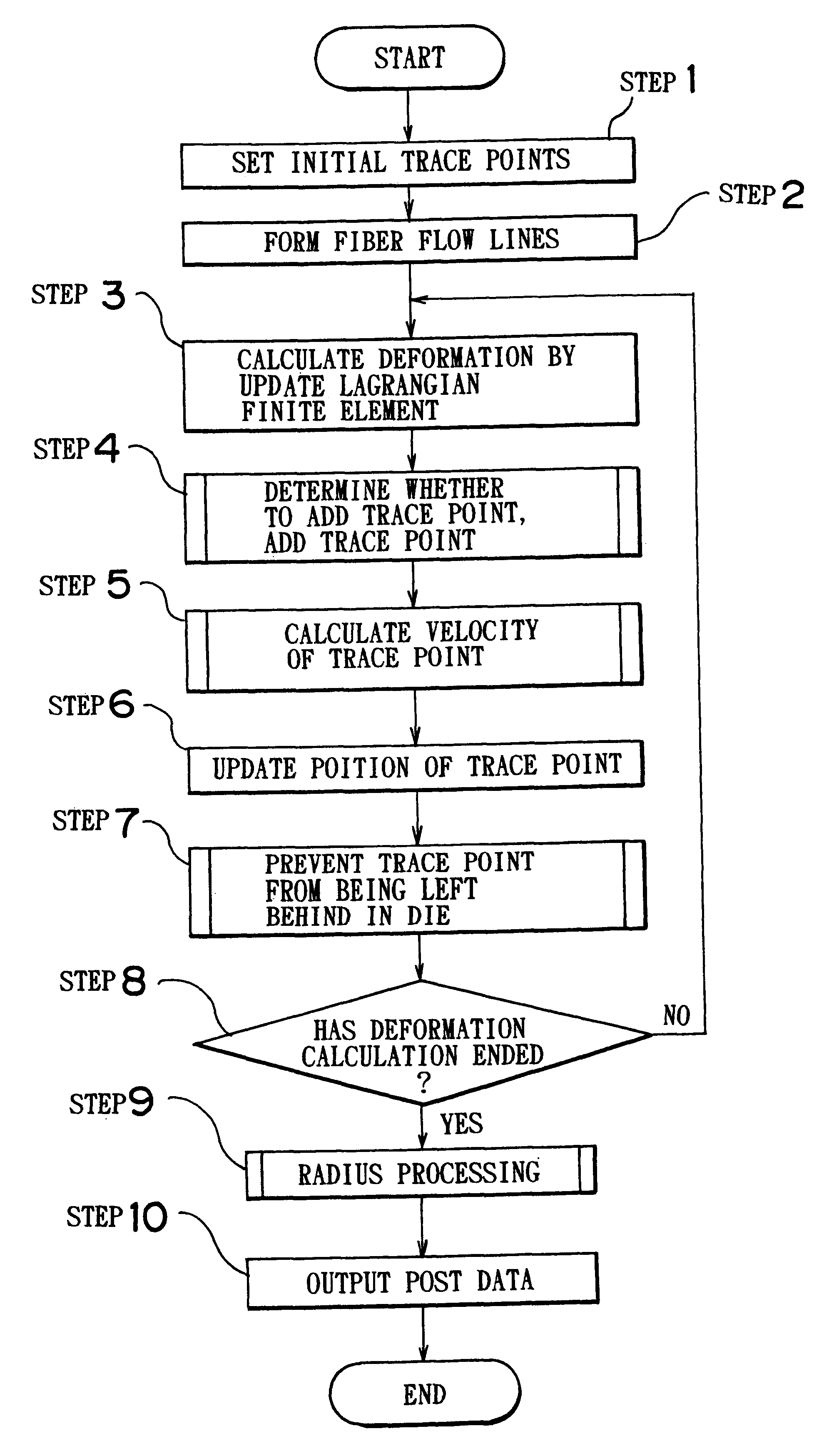
A preferred embodiment of the present invention will be described in detail hereinafter with reference to the accompanying drawings. In a forging process analyzing method according to this embodiment, analysis is performed by a computer, such as a personal computer, a workstation or the like, by a procedure as illustrated by the flowchart of FIG. 1. A program needed to cause the computer to execute necessary processes is recorded in a medium, for example, a floppy disk, a compact disk or the like. The computer reads the program recorded on the medium, and executes processes described below.

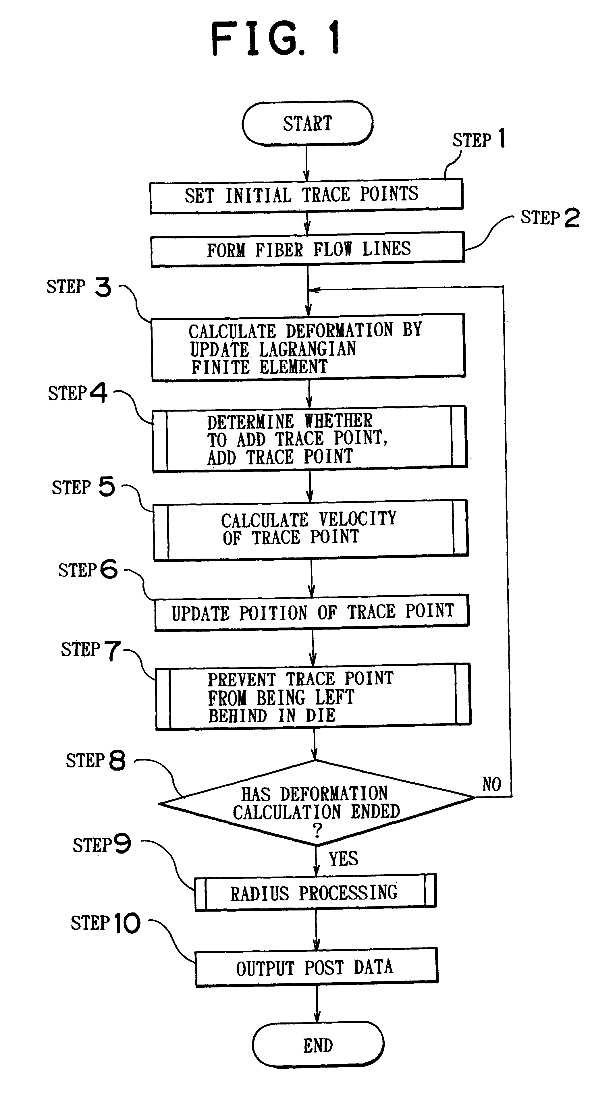
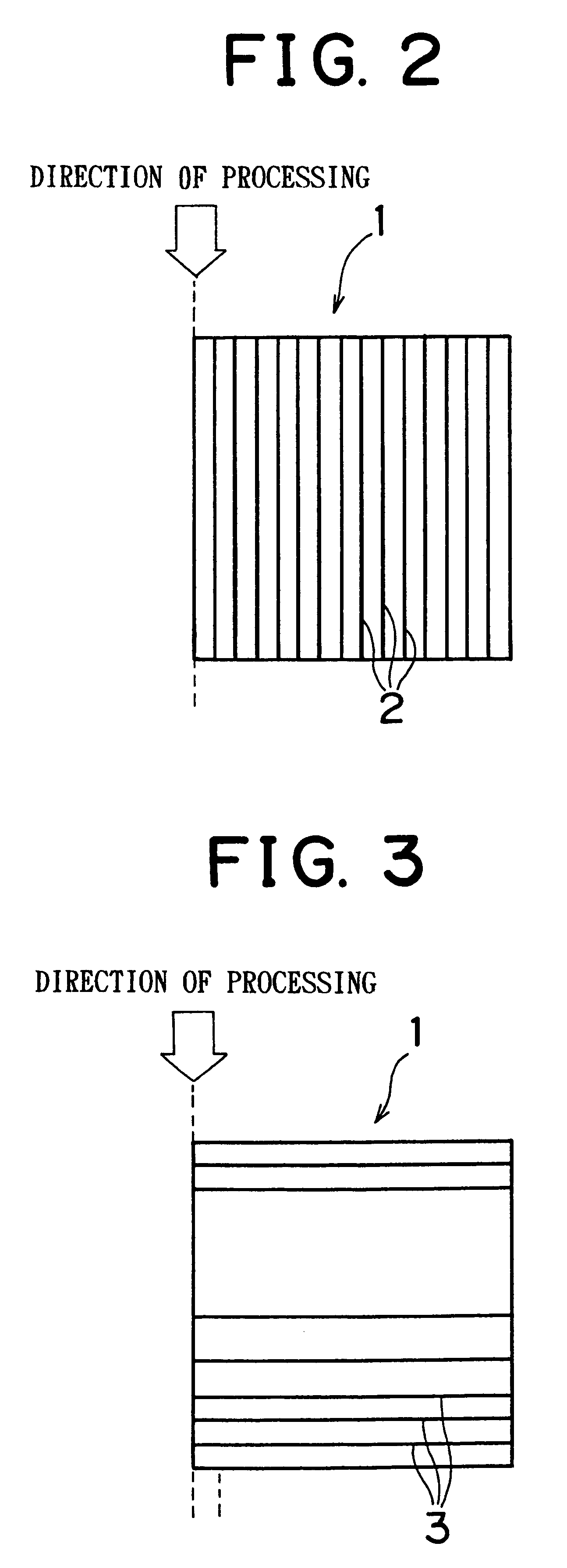
In steps 1 and 2, the computer sets many trace points in the interior of a workpiece of steel or the like. In setting trace points, the computer take into account the initial shape of the workpiece, the target shape, condition of friction against a tools, and other information. The group of trace points thus set are used to express a fiber flow line of the workpiece. That is, straight line segment...


PUM

PropertyMeasurementUnit
Lengthaaaaaaaaaa
Thicknessaaaaaaaaaa
Shapeaaaaaaaaaa

Abstract

In a forging process analyzing method, many trace points are set in a workpiece. Lines connecting the trace points express fiber flow lines. The fiber flow lines may be imaginary ones that are irrelevant to real fiber flow lines. By applying a technique of a finite element method to the fiber flow lines, deformation calculation is performed. A new trace point is added between trace points when the distance therebetween is great. The velocity of each trace point cause by deformation is calculated, and the position of each trace point is updated. When any trace point in an element is left behind in a die, the left-behind phenomenon is prevented by converting the shape of the element while the crossing of fiber flow lines is prevented. A radius is set for each trace point. The radius of each trace point is adjusted so as to eliminate off-boundary extension and overlap of fiber flow lines.

Description

INCORPORATION BY REFERENCEThe disclosure of Japanese Patent Application No. HEI 10-309920 filed on Oct. 30, 1998 and No. HEI 11-223755 filed on Aug. 6, 1999, each including the specification, drawings and abstract, is incorporated herein by reference in its entirety.1. Field of the InventionThe present invention relates to analysis of a forging process of a material and, more specifically, to a technology for analyzing and / or predicting deformation of a workpiece caused due to the forging process performed thereon by setting fiber flow lines in the interior of the workpiece and calculating displacements of the fiber flow lines caused by the forging process. The invention relates particularly to a technology capable of analysis taking three-dimensional information into account.2. Description of the Related ArtForging processes, such as pressing or the like, sometimes suffer from defects, such as forging defects, dead metal, buckling or the like, depending on the combination of whethe...

Claims


Application Information

Patent Timeline
IPC IPC(8): B21C51/00B21J5/00G01N3/02G01N3/00
CPCB21C23/001B21C51/00B21J1/025B21J5/00G01N2203/0216G01N2203/0248
Inventor ATSUMI, YOSHITAKAMATSUOKA, NAOKIAKASHI, TADAOYANO, HIROSHITAKEUCHI, MASAHIKONAKANISHI, KOKICHI
Owner TOYOTA JIDOSHA KK
Why Eureka
Try Eureka