
Automated solution injection-discharge system and automated peritoneal dialysis system

a technology of injection-discharge system and injection-discharge system, which is applied in the direction of dialysis system, peritoneal dialysis, suction device, etc., can solve the problems of user error, contamination of the dialysis system connector, and troublesome patients

Inactive Publication Date: 2002-12-10
JMS CO LTD
View PDF13 Cites 75 Cited by
  • Summary
  • Abstract
  • Description
  • Claims
  • Application Information

AI Technical Summary

Benefits of technology

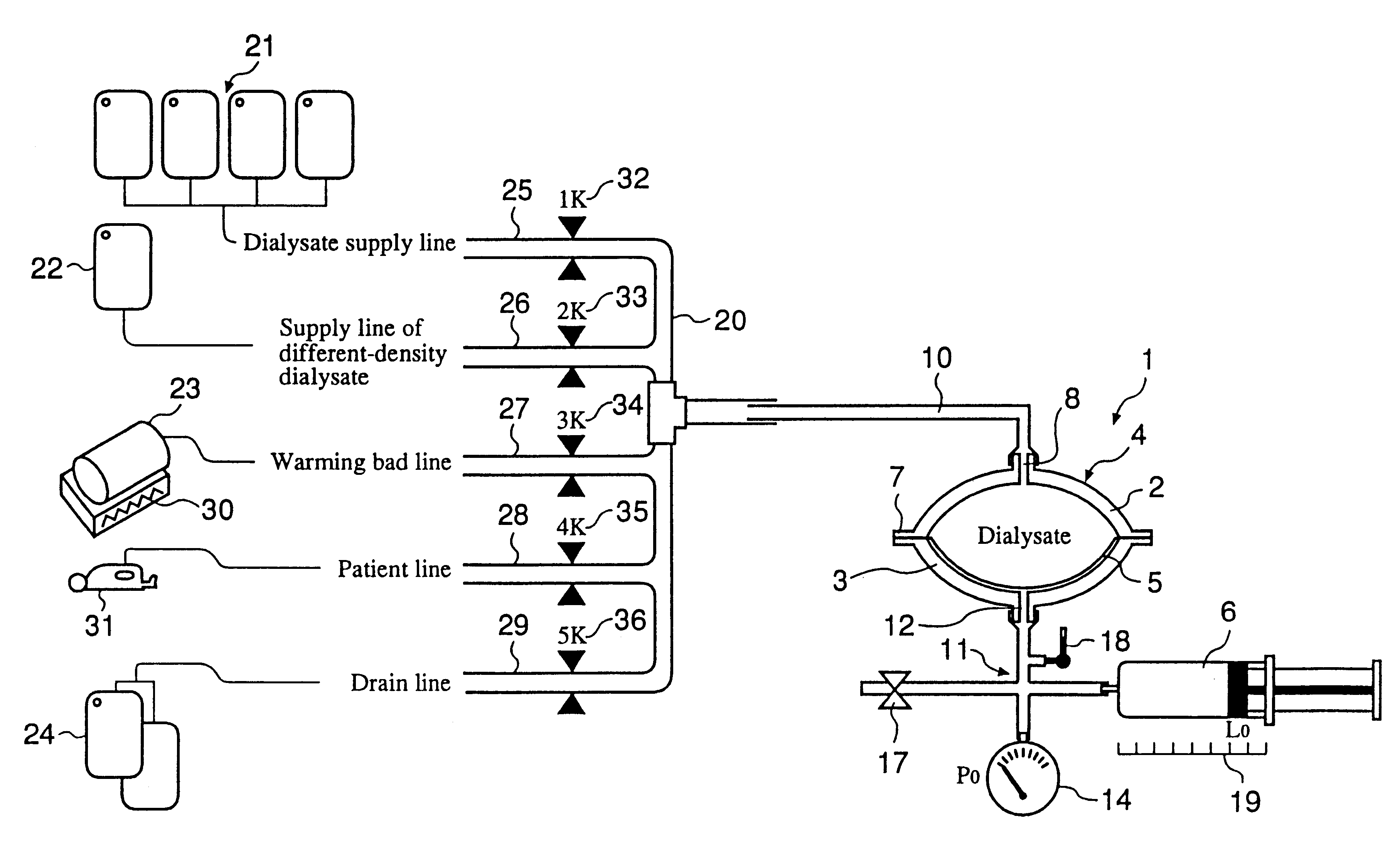
The first object of the present invention is to provide a compact, simple-structured, and user-friendly automated solution injection-discharge system ensuring safe operation of injected and discharged solution. Especially when the automated solution injection-discharge system is used as an APDS system to supply and discharge a dialysate and a patient's drain, the object is to provide an automated solution injection-discharge system (1) which is free of contamination and operation mistakes, and (2) which can accurately control the injected dialysate volume and the discharged dwell solution volume even when a patient does not maintain a fixed posture while replacing the solution.

Problems solved by technology

In this treatment, however, a patient has to exchange bags several times, desorb connectors, and open and close a clamp (a closing gear) every day, which is troublesome to the patient.
An operating mistake by a patient, especially by a sight-or hand-impaired patient, may contaminate the connector of the dialytic system.
Moreover, a user may make mistakes in injecting and discharging.
However, the head drop mechanism has some demerits in that the patient must maintain a fixed posture, and the system is relatively large in size.
However, there is a possibility that dialysate may be excessively injected into a patient because the roller pump may rotate without reference to the prescribed volume of solution.
Another possibility is that the peritoneum may be damaged if the roller pump automatically sucks when a small amount of dialysate remains in the peritoneal cavity.
First, the system is large in size and expensive because a load cell weighs the filled and drained volumes of solution.
Second, the control system is complicated and expensive because each closing gear, which is installed on each conduit connected between a dialysate bag, a drain bag, a patient's peritoneal catheter, a warming gear, and a reservoir for compounding and warming a solution, operates separately.

Method used


Image

  • Automated solution injection-discharge system and automated peritoneal dialysis system
  • Automated solution injection-discharge system and automated peritoneal dialysis system
  • Automated solution injection-discharge system and automated peritoneal dialysis system

Examples


Embodiment Construction

is provided based on the drawings.

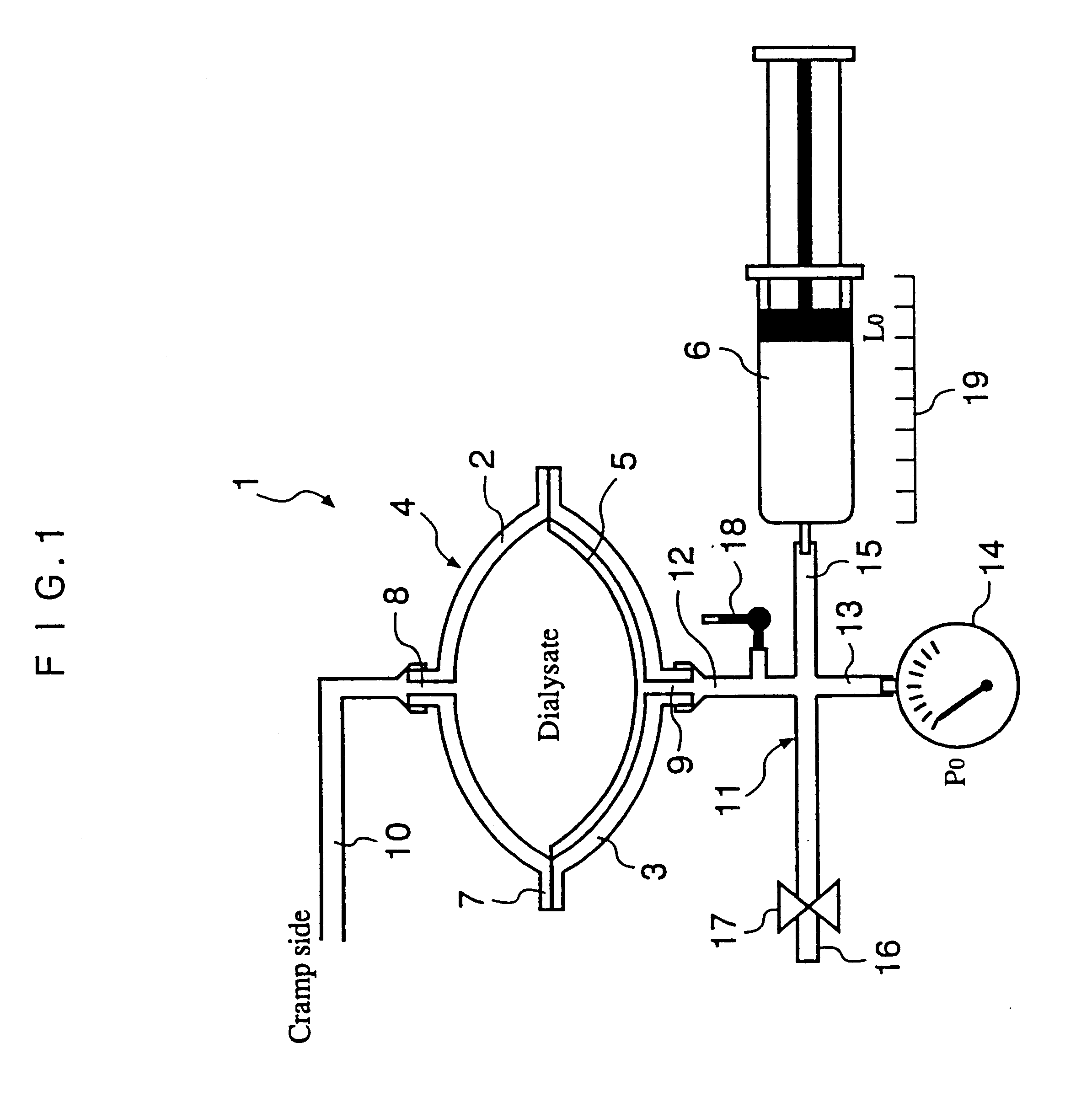
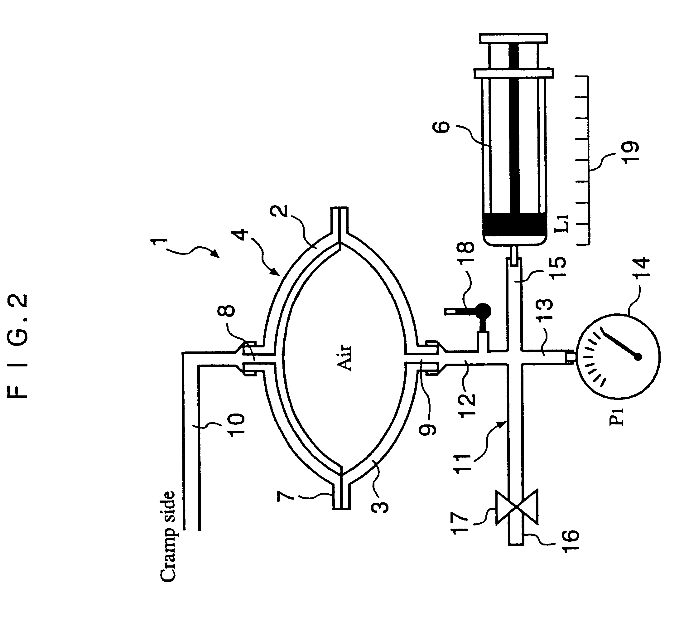
FIGS. 1 and 2 outline the automated solution injection-discharge system of the APDS, using a diaphragm related to the present invention that sucks or introduces a peritoneal dialysate or a drain from a peritoneum. In FIG. 2, the diaphragm of FIG. 1 is inverted to the upper position. In FIGS. 1 and 2, the numbers are identical for the same machine configurations.

In FIG. 2, automated solution injection-discharge system 1 is provided with a chamber 4 equipped with a hemispherical top cover 2 and a hemispherical bottom cover 3, a diaphragm 5 installed in chamber 4, and a driving device 6 to move diaphragm 5. Diaphragm 5 is made of a synthetic resin thin film such as silicone, vinyl chloride resin, natural rubber, thermoplastic elastomer, or other materials. The diaphragm is ordinarily approximately 0.2 to 0.5 mm in thickness. Top cover 2 and bottom cover 3 are preferably made of hard transparent plastic such as polycarbonate, vinyl chloride resin, polyp...


PUM


Abstract

The automated solution injection-discharge system is used as an APDS system to supply and discharge a dialysate and a patient's drain. And an automated solution injection-discharge system provides free of contamination and operation mistakes, and can accurately control the injected dialysate volume and the discharged dwell solution volume even when a patient does not maintain a fixed posture while replacing the solution.

Description

The present invention relates to an automated solution injection-discharge system which automatically injects a dialysate into a patient's peritoneal cavity and discharges the dialysate after the appointed time. In addition, the present invention relates to an automated peritoneal dialysis system (APDS) which employs the above-mentioned automated solution injection-discharge system.Dialytic treatment has advantages such as (1) medical expenses are inexpensive, (2) the patient does not require frequent outpatient treatment, and (3) the patient can easily return to society. As a result, medical facilities in Japan have increasingly introduced dialytic treatment.In continuous ambulatory peritoneal dialysis (CAPD), a patient can easily replace the dialysate at home at moderate cost. Many peritoneal dialytic patients have recently received CAPD treatment. In this treatment, however, a patient has to exchange bags several times, desorb connectors, and open and close a clamp (a closing gea...

Claims


Application Information

Patent Timeline
IPC IPC(8): A61M1/28
CPCA61M1/28A61M1/281
Inventor MIURA, HIROMUYAMASHITA, KATSUYA
Owner JMS CO LTD
Learn More