Liquid crystal electro-optical device and electronic appliance

a technology of electrooptical devices and liquid crystals, applied in the direction of optics, static indicating devices, instruments, etc., can solve the problems of high light loss of reflective lcd, large volume of crts, weight and power consumption,

Inactive Publication Date: 2002-12-10
SEMICON ENERGY LAB CO LTD
View PDF4 Cites 31 Cited by
  • Summary
  • Abstract
  • Description
  • Claims
  • Application Information

AI Technical Summary

Problems solved by technology

However, the CRTs are large in volume, weight and power consumption, and particularly not suited as a display unit with a large screen.
However, it is that the reflective LCD undergoes higher light loss as compared to the transmission LCD.
Consequently, the greatest problem with the reflective LCD hinges on how much incoming light is effectively utilized.
This is because if the reflectivity is low the utilization efficiency of light considerably decreases thereby darkening the whole display.
Meanwhile, even if the backlight light amount is increased to increase display brightness, countermeasures will be required against problems of increasing power consumption and heat generation thus resulting in cost up.
Incidentally, although silver electrodes are charac

Method used


Image

  • Liquid crystal electro-optical device and electronic appliance
  • Liquid crystal electro-optical device and electronic appliance
  • Liquid crystal electro-optical device and electronic appliance

Examples


embodiment 1

Now one embodiment of the present invention will be described. In this embodiment, explanation is made for a case that the invention is applied to a reflective LCD for a single plate type projector.

The reflective LCD of this embodiment is structured by pixels arranged corresponding to three primary colors of red, green and blue in an area corresponding to unit pixels. That is, the incoming light from a light source (white light) is passed through a color filter where it is turned into a light having a wavelength corresponding to each of red, green or blue color to be incident onto a pixel corresponding to the color.

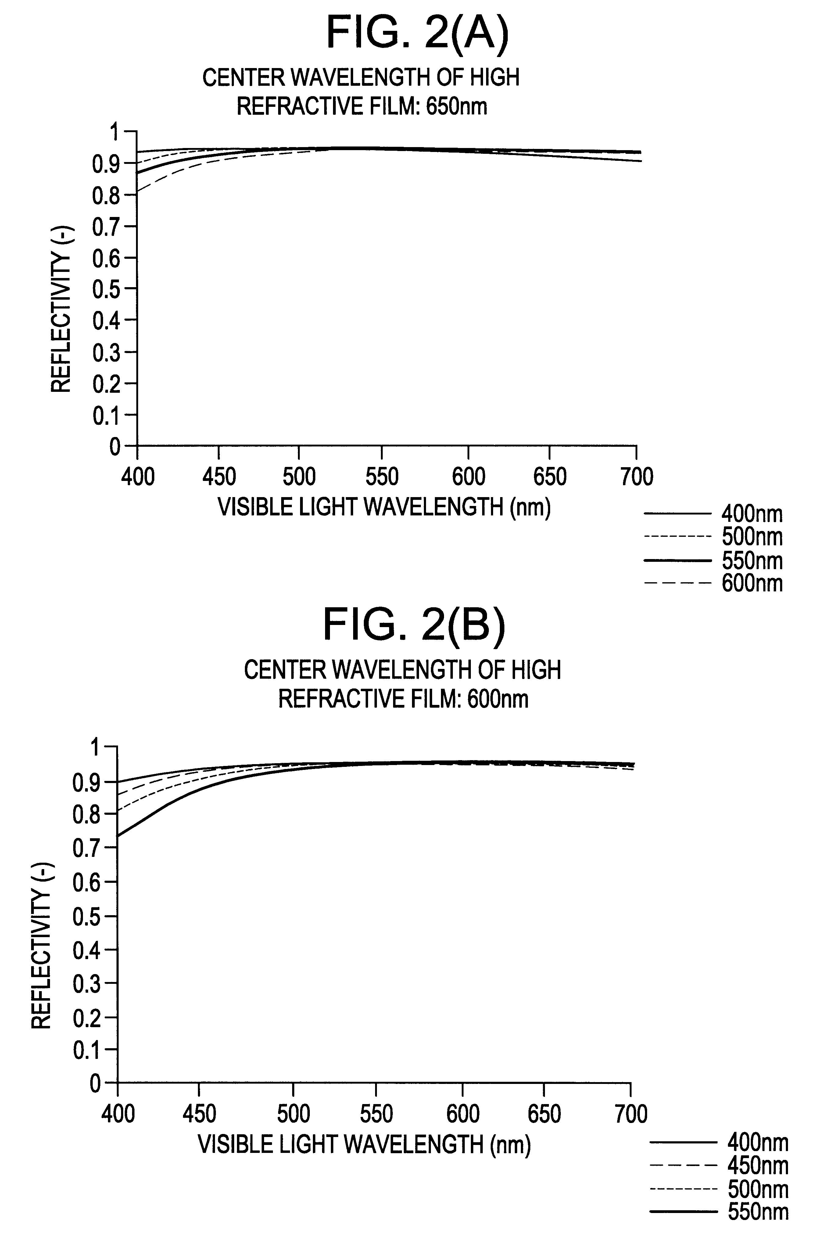
Consequently, in this embodiment red, green and blue of wavelength light must be efficiently reflected by same-structured pixel electrodes. A flat reflection characteristic is required without having a dependency on wavelength within a visible light range (approximately 400-700 nm).

Also, in this embodiment explanation is made on a case of adopting a simplest two-layered s...

embodiment 2

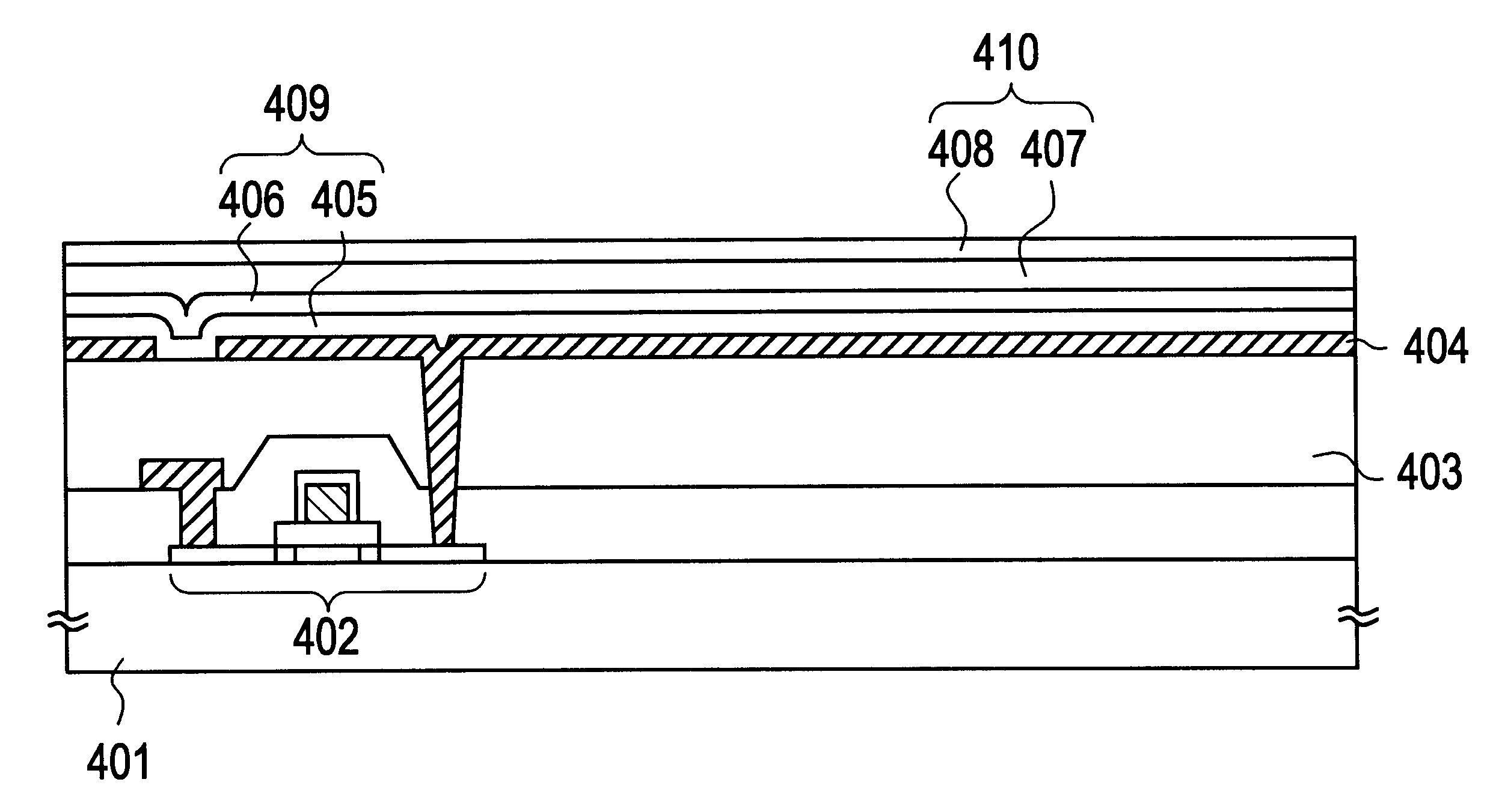
This embodiment explains on a structure having two dielectric multi-layered films (i.e. dielectric film four-layered structure) wherein one multi-layered film is formed by a low refractive film and a high refractive film. Explanation is based on FIG. 4.

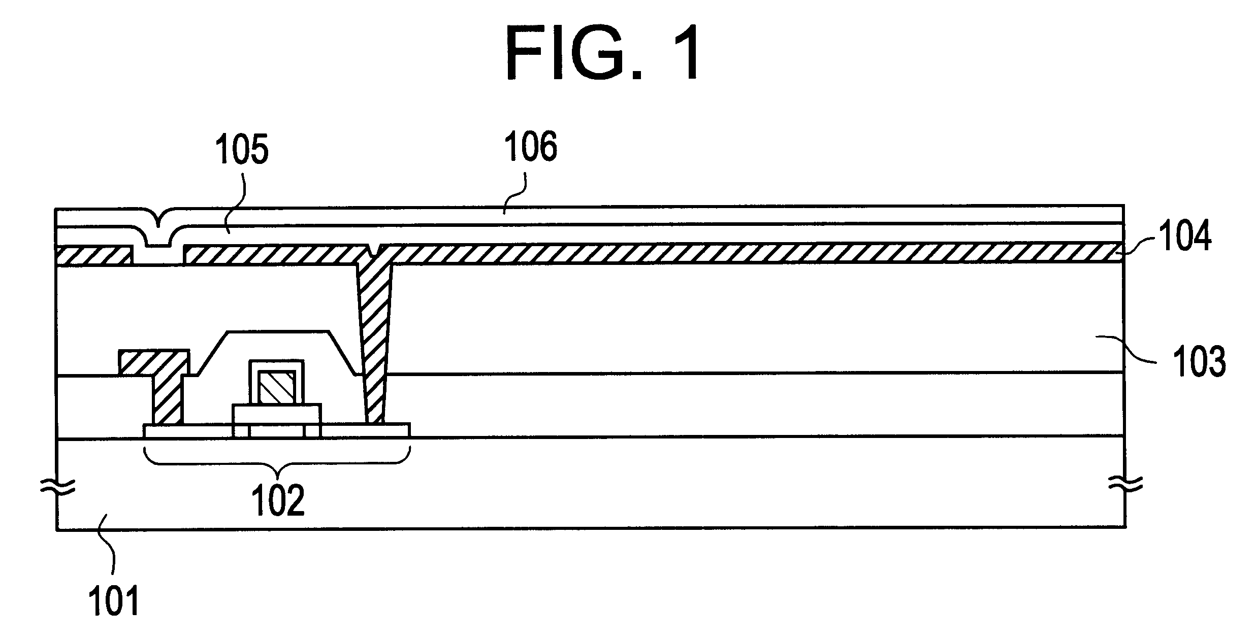
In FIG. 4(A), 401 is a substrate having an insulation surface and 402 is a TFT formed by a known means. The TFT 402 is covered with a planar film 403 over which a pixel electrode 404 is provided connecting to the TFT 402 through a contact hole. The pixel electrode 404 in this embodiment employs an aluminum film containing 1 wt % of titanium. This material is of course not limitative.

In this embodiment, over the pixel electrode 404 are formed a first dielectric film 405 (low refractive film), a second dielectric film 406 (high refractive film), a third dielectric film 407 (low refractive film) and a fourth dielectric film 408 (high refractive film). The first and third dielectric films used a material having a somewhat low refractive i...

embodiment 3

A pixel structure of this embodiment is explained with reference to FIG. 7. Incidentally, the structure is similar to that of FIG. 4 and the same parts to those of FIG. 4 are denoted by the same reference characters. This embodiment is formed, on a pixel electrode 404, one another a first dielectric film 701 (low refractive film), a second dielectric film 702 (high refractive film), a third dielectric film 703 (low refractive film), and a fourth dielectric film 704 (high refractive film).

The first and third dielectric films employed a material having a somewhat low refractive index (n.sub.L) of 1.2-1.6, while the second and fourth dielectric films used a material having a somewhat high refractive index (n.sub.H) of 1.8-2.5.

In this embodiment a dielectric multi-layered film formed by the first and second dielectric films is referred to as a dielectric (C) 705 for the convenience sake, while a dielectric multi-layered film formed by the third and fourth dielectric films is as a dielec...


PUM


Abstract

A liquid crystal display device is realized which is improved in light reflectivity on pixel electrodes to provide brightness at low cost and low power consumption. A dielectric multi-layered film having a first dielectric film (low refractive film) 105 and a second dielectric film (high refractive film) 106 is formed on a pixel electrode 104 connected to a TFT 102 formed on a substrate 101 having an insulation surface. This dielectric multi-layered film is determined in refractive index (n), center wavelength (lambd) and film thickens (d) according to an equation nd=lambd/4, to give an enhanced reflection effect.

Description

1. Field of the InventionThe present invention relates to a structure of a display device utilizing a liquid crystal as a display medium (called liquid crystal display device or LCD). More particularly, the invention is concerned with a technology on an electrode structure for applying a predetermined voltage to the liquid crystal.2. Description of the Related ArtCRTs are most popular as conventional displays. However, the CRTs are large in volume, weight and power consumption, and particularly not suited as a display unit with a large screen. Under such a situation, attentions have recently being drawn to liquid crystal display devices (hereinafter referred to as "liquid crystal panel") that are advantageous over the CRTs in respect of light-weight, low power consumption and large display screen.Although the drive methods differ depending upon a liquid crystal kind used in a liquid crystal panel, there is known a drive method using liquid crystal birefringence. This is a drive meth...

Claims


Application Information

Patent Timeline
IPC IPC(8): G02F1/1335G02F1/13G02F1/1343G02F1/136G02F1/1368
CPCG02F1/133502G02F1/133553
Inventor SATAKE, RUMONISHI, TAKESHIHIRAKATA, YOSHIHARU
Owner SEMICON ENERGY LAB CO LTD
Why Eureka
Try Eureka