Valve for controlling liquids

Inactive Publication Date: 2003-01-07
ROBERT BOSCH GMBH
View PDF13 Cites 17 Cited by
  • Summary
  • Abstract
  • Description
  • Claims
  • Application Information

AI Technical Summary

Problems solved by technology

Compensating for changes in length of the piezoelectric actuator, the valve member or the valve housing by means of the hydraulic chamber disposed between two pistons requires a complicated construction, however, and is problematic in terms of the incident leakage losses and the refilling of the hydraulic chamber.
A disadvantage of this is that the sprin

Method used


Image

  • Valve for controlling liquids
  • Valve for controlling liquids

Examples


Example

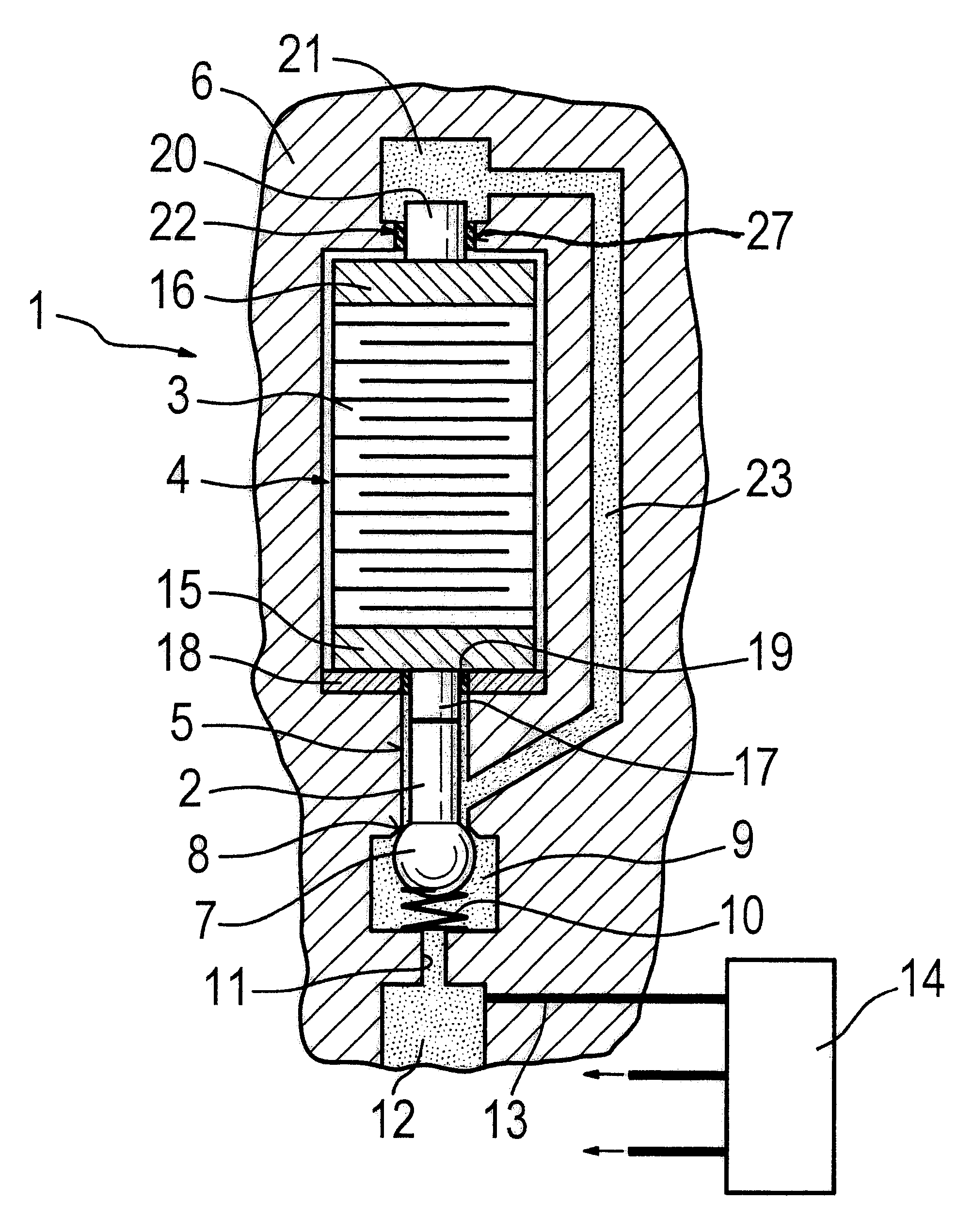
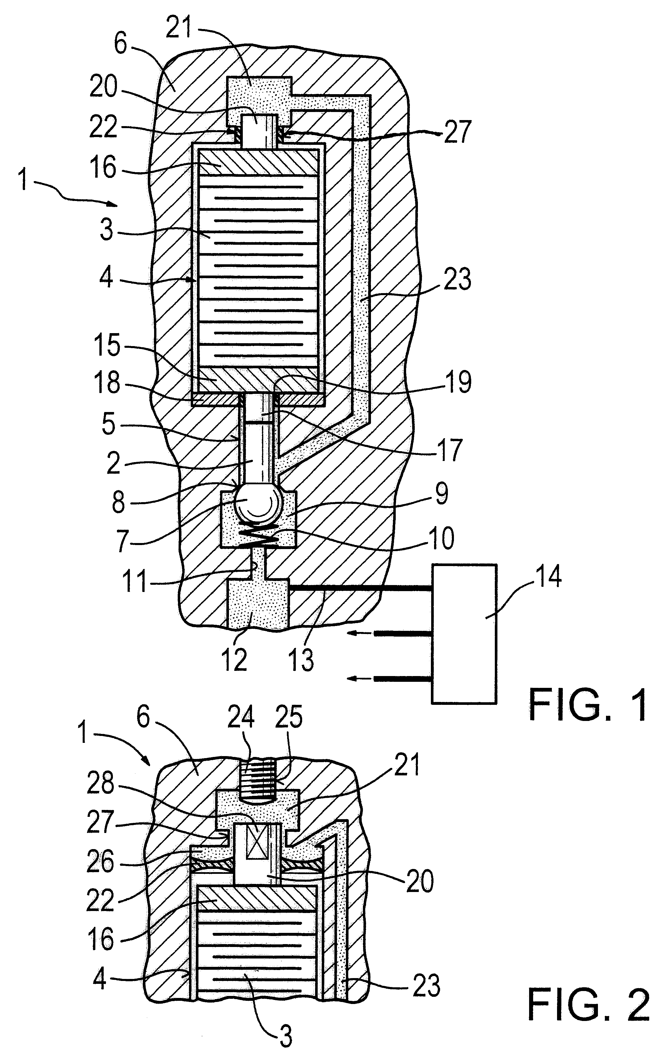
The first exemplary embodiment shown in FIG. 1 illustrates a use of the valve of the invention in a fuel injection valve 1 for internal combustion engines of motor vehicles. The fuel injection valve 1 is embodied here as a common rail injector, and the fuel injection is controlled via the pressure level in a valve control chamber 12, which is connected to a high-pressure supply.

For setting an injection onset, injection duration, and injection quantity via force ratios in the fuel injection valve 1, a valve member 2 is triggered via a piezoelectric actuator 3, which is disposed on the side of the valve member 2, remote from the combustion chamber, in a piezoelectric chamber 4.

The pistonlike valve member 2 is disposed axially displaceably in a bore 5, embodied as a longitudinal bore, of a valve body 6, and on its end toward the combustion chamber it has a ball-shaped valve head 7 forming a valve closing member. The valve head 7 cooperates with a seat 8, embodied on the valve body 6, a...


PUM


Abstract

A valve for controlling fluids is embodied with a piezoelectric actuator (3) for actuating a valve member (2) that on one end has a valve head (7), forming a valve closing member, that cooperates with a seat (8) provided on the valve body (6) for opening and closing the valve (1). On a side of the piezoelectric actuator (3) remote from the valve member (2), a hydraulic chamber (21) is provided, which communicates, via at least one hydraulic line (23), with a bore (5) of the valve member (2) that is sealed from the piezoelectric actuator (3), and into which bore a piston (20) connected to the piezoelectric actuator (3) can plunge; the hydraulic chamber (21) is embodied as a hydraulic spring, which with its spring force on the piston (20) connected to the piezoelectric actuator (3) act as the prestressing element and the tolerance compensating element. The valve is intended in particular as a component of a fuel injection valve.

Description

PRIOR ARTThe invention relates to a valve for controlling fluids. From European Patent Disclosure EP 0 477 400 A1, a valve is already known which is actuatable via a piezoelectric actuator. This known valve has an arrangement for an adaptive mechanical tolerance compensation, effective in the stroke direction, for a travel transformer of the piezelectric actuator, in which the deflection of the piezoelectric actuator is transmitted via a hydraulic chamber.The hydraulic chamber, which functions as a so-called hydraulic step-up means, encloses a common compensation volume between two pistons defining this chamber, of which one piston is embodied with a smaller diameter and is connected to a valve member to be triggered, and the other piston is embodied with a larger diameter and is connected to the piezoelectric actuator. The hydraulic chamber is fastened between the two pistons in such a way that the actuating piston of the valve member, which piston is retained in its position of re...

Claims


Application Information

Patent Timeline
IPC IPC(8): F02M59/46F02M59/00F02M47/02F02M45/04F02M47/00F02M51/00F02M61/16F02M61/20F16K31/02
CPCF02M47/027F02M63/0026Y10S137/906
Inventor MATTES, PATRICK
Owner ROBERT BOSCH GMBH
Why Eureka
Try Eureka