Method and an arrangement in a radio system

a radio system and method technology, applied in the direction of transmission monitoring, receiver monitoring, wireless communication, etc., can solve the problems of high cost, cumbersome manual inspection, and damage to different parts of the base station equipment, and achieve the effect of simple but efficien

Inactive Publication Date: 2003-01-07
TELEFON AB LM ERICSSON (PUBL)
View PDF14 Cites 22 Cited by
  • Summary
  • Abstract
  • Description
  • Claims
  • Application Information

AI Technical Summary

Benefits of technology

is to provide a simple but efficient arrangement for testing receiver antennas in radio base stations, provided with multiple receiver antennas.

Problems solved by technology

One problem encountered in such systems is to determine the integrity of radio base stations used in the systems when they have been installed.
Different parts of the base station equipment may be damaged from vandalism or natural causes such as, for instance, moisture.
Cellular systems, however, normally require large numbers of base stations in order to achieve sufficient coverage, and therefore manual inspection becomes very cumbersome and expensive.
When it comes to receiver antennas, however, the task is more complicated.
This adds not only cost but also complexity, especially if multiple receiver antennas are used to provide antenna diversity.
The reverse attenuation of the TMA is very high and therefore VSWR measurements become very difficult.
Another disadvantage with the VSWR approach is that the receiver and transmitter antennas of the system have to be tested separately, one at a time.
Such systems function properly, however, only for testing duplex antennas, and require additional frequency shifting means.
It is to be noted that VSWR measurements on duplex antennas also may be difficult.
When three filters are series connected the total attenuation make measurements difficult.

Method used


Image

  • Method and an arrangement in a radio system
  • Method and an arrangement in a radio system
  • Method and an arrangement in a radio system

Examples


Embodiment Construction

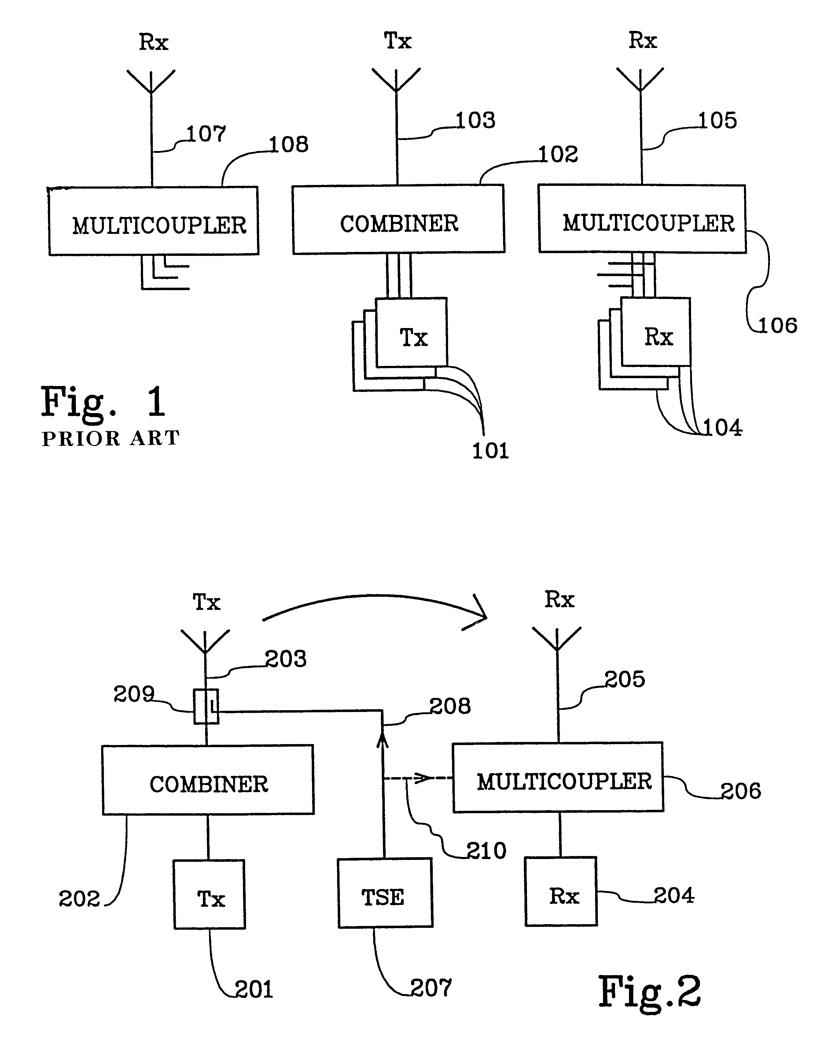
FIG. 1 illustrates, schematically, a radio base station transceiver according to prior art. The base station transceiver involves a plurality of transmitter units 101. The transmitter units are connected to a combiner 102 which provides separation between the different transmitter units 101 and directs radio frequency signals produced by the transmitter units towards a transmitter antenna 103. The combiner 102 consists of a number of resonant filters.

The base station transceiver furthermore involves a number of receiver units 104. The receiver units are connected to at least one receiver antenna 105 via a multicoupler 106, which amplify incoming signals and couples these signals to different receiver units. The receiver units may be coupled to an auxiliary antenna 107 via an auxiliary multicoupler 108 to provide antenna diversity. More than one auxiliary antenna may be used. It is to be noted that a transmitter unit and a receiver unit may be applied as different portions of a print...


PUM


Abstract

The invention relates to a method and an arrangement for testing receiver antennas in radio base stations. A low-power RF signal is emitted, having a frequency corresponding to the carrier frequency of the receiver. This signal is coupled to a transmitter antenna to be transmitted to a receiver antenna of the same system. The signal thus received is analysed by the receiver in order to determine the integrity of the receiver antenna.

Description

The invention relates to a method and an arrangement for monitoring the condition of base station antennas in cellular radio systems. Such systems provide voice and data communication services. Several standards such as TACS, AMPS, D-AMPS, NMT and GSM have been established.DESCRIPTION OF RELATED ARTOne problem encountered in such systems is to determine the integrity of radio base stations used in the systems when they have been installed. Different parts of the base station equipment may be damaged from vandalism or natural causes such as, for instance, moisture. The operator of the system must detect any occurring error promptly in order to achieve sufficient coverage and service level.One way of determining the functionality of a radio base station is to perform a manual inspection. Service personnel then inspect the base station visually and perform on-site tests. Cellular systems, however, normally require large numbers of base stations in order to achieve sufficient coverage, ...

Claims


Application Information

Patent Timeline
Patent Type & Authority Patents(United States)
IPC IPC(8): H04B17/00H04B7/26
CPCH04B17/20
Inventor BORGSTRAND, RONNY
Owner TELEFON AB LM ERICSSON (PUBL)
Why Eureka
Try Eureka