Image-forming apparatus and method of manufacturing the same
a technology of image-forming apparatus and manufacturing method, which is applied in the direction of instruments, tubes with screens, discharge tubes, etc., can solve the problems of degrading the vicinity of electron sources, surface creepage may occur via the surface of the supporting frame, and display may not be conducted normally
- Summary
- Abstract
- Description
- Claims
- Application Information
AI Technical Summary
Problems solved by technology
Method used
Image
Examples
example 1
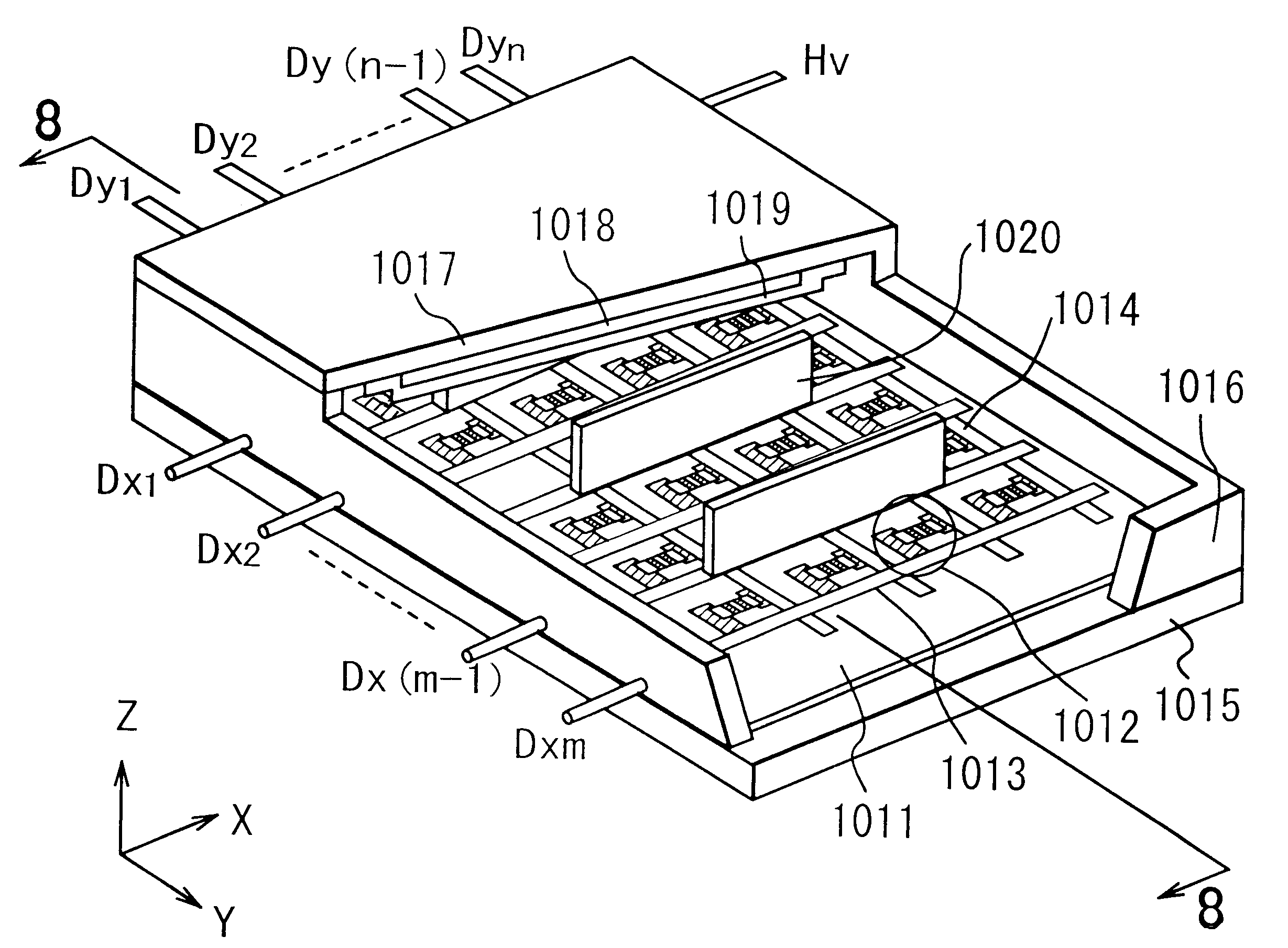
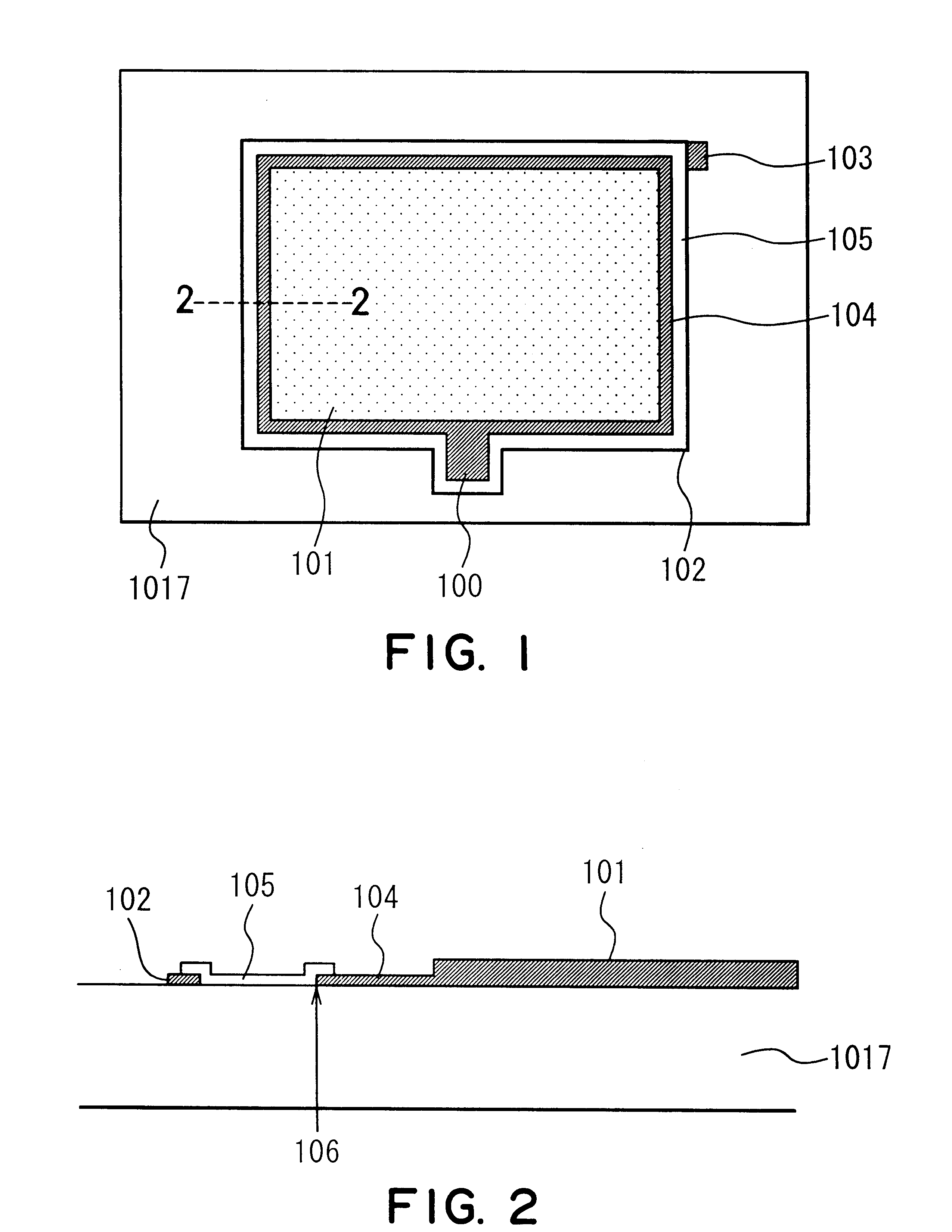
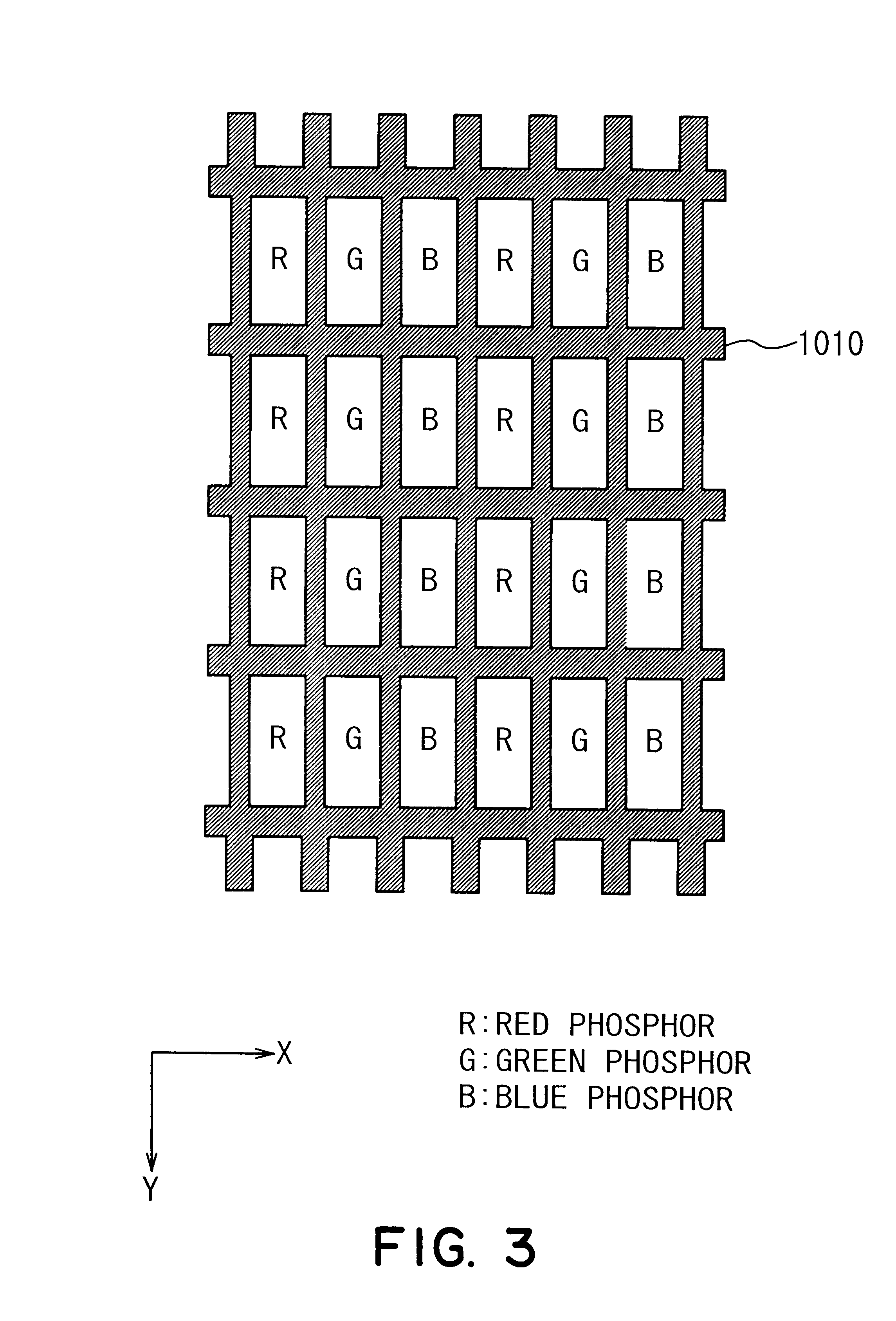
In the present example, two kinds of resistant films are formed between an image display region and an electroconductive member. FIG. 9 is a cross-sectional view showing the resistant films. Herein, reference numeral 1017 denotes a face plate substrate, 1019 denotes a metal back, 102 denotes an electroconductive member, 104 denotes a first resistant film (first resistant member), 105 denotes a second resistant film (second resistant member), 106 denotes a resistance border portion, and 401 denotes phosphors and a black matrix. The metal back 1019 and the phosphors and the black matrix 401 constitute an image display region.
First, as the first resistant film 104, WGeN (nitride of tungsten and germanium) was formed to a film with a thickness of about 250 [nm]. The first resistant film 104 was formed by sputtering for 20 minutes under the conditions of a total pressure of 1.5 [Pa], an Ar flow rate of 50 [sccm], an N.sub.2 flow rate of 5 [sccm], and a W input power of 239 [W], and a Ge ...
example 2
In the present example, a first resistant film (first resistant member) was made of ITO. FIG. 10 shows a cross-sectional view thereof. Reference numeral 1017 denotes a face plate substrate, 1019 denotes a metal back, 102 denotes a conductive member, 104 denotes a first resistant film, 105 denotes a second resistant film, 106 denotes a resistance border portion, and 401 denotes phosphors and a black matrix. The metal back 1019 and the phosphors and the black matrix 401 constitute an image display region.
In the present example, an ITO film was also formed in the image display region, and the first resistant film 104 was continuously formed (104 in the figure) at the same time under the same conditions as shown in FIG. 10. Furthermore, in the present example, the ITO film was formed before forming the electroconductive member 102 and a high voltage applying terminal abutting portion (not shown). The ITO film has a thickness of about 200 [nm], and a sheet resistance of about 10.sup.6 [....
example 3
In the present example, WGeN is used for a resistant film, and sputtering conditions are varied, whereby the resistances of the first and second resistant films are changed. The cross-sectional structure in the present example is the same as that in Example 1 (FIG. 9). Regarding the film-formation conditions, only an input power is changed, and the remaining conditions are a total pressure of 1.5 [Pa], an Ar flow rate of 50 [sccm], an N.sub.2 flow rate of 5 [sccm], and a Ge electric power of 600 [W]. In forming the first resistant film, a W (tungsten) input power was set to 230 [W] to obtain a sheet resistance of about 4.times.10.sup.9 [.OMEGA. / square]. In forming the second resistant film, a W (tungsten) input power was set to 180 [W] to obtain a sheet resistance of about 2.times.10.sup.12 [.OMEGA. / square].
An image-forming apparatus was formed by using the above-mentioned face plate. The same effects as those in Example 1 were obtained. In this case, the material of the first resis...
PUM
 Abstract
Description
Claims
Application Information
 - R&D
- Intellectual Property
- Life Sciences
- Materials
- Tech Scout
- Unparalleled Data Quality
- Higher Quality Content
- 60% Fewer Hallucinations
Browse by: Latest US Patents, China's latest patents, Technical Efficacy Thesaurus, Application Domain, Technology Topic, Popular Technical Reports.
© 2025 PatSnap. All rights reserved.Legal|Privacy policy|Modern Slavery Act Transparency Statement|Sitemap|About US| Contact US: help@patsnap.com


