
Electrostrictive graft elastomers

a technology of elastomers and grafts, applied in the field of graft elastomers, can solve the problems of undetectable heavy and brittle ceramics, low modulus of polymeric materials, and low actuation authority

Inactive Publication Date: 2003-02-04
NASA
View PDF16 Cites 32 Cited by
  • Summary
  • Abstract
  • Description
  • Claims
  • Application Information

AI Technical Summary

Benefits of technology

It is also a primary object of the present invention to provide a process for producing an elastomer of high strain energy density, low mass, excellent conformability and processability, and mechanical and electrical toughness for durability.
In the second preferred embodiment of the present invention, a process is presented which includes providing a graft elastomer having a backbone molecule which is a non-crystallizable, flexible macromolecular chain and a grafted polymer which forms polar graft moieties with backbone molecules. An electric field is applied to this graft elastomer to rotate the polar graft moieties, advantageously into substantial polar alignment, resulting in an elastomer of high strain energy density. In this process, the backbone molecule of the graft elastomer is advantageously a member selected from the group consisting of silicones, polyurethanes, polysulfides, nitrile rubbers, polybutenes, and fluorinated elastomers, such as chlorotrifluoroethylene-vinylidene fluoride copolymers. In this process, the grafted polymer is a homopolymer or a copolymer, preferably a member selected from the group consisting of poly(vinylidene fluoride) and poly(vinylidene fluoride-trifluoroethylene) copolymers, and the polar graft moieties are polar crystal phases and physical entanglement sites with the backbone molecules.

Problems solved by technology

However, piezoelectric polymers such as poly(vinylidene fluoride) provide very low strains, while the ceramics are undesirably heavy and brittle, and provide low strains.
However, these polymeric materials have very low moduli, and consequently possess very little actuation authority.

Method used


Image

  • Electrostrictive graft elastomers
  • Electrostrictive graft elastomers
  • Electrostrictive graft elastomers

Examples


Embodiment Construction

should be read with reference to the accompanying Drawings, wherein:

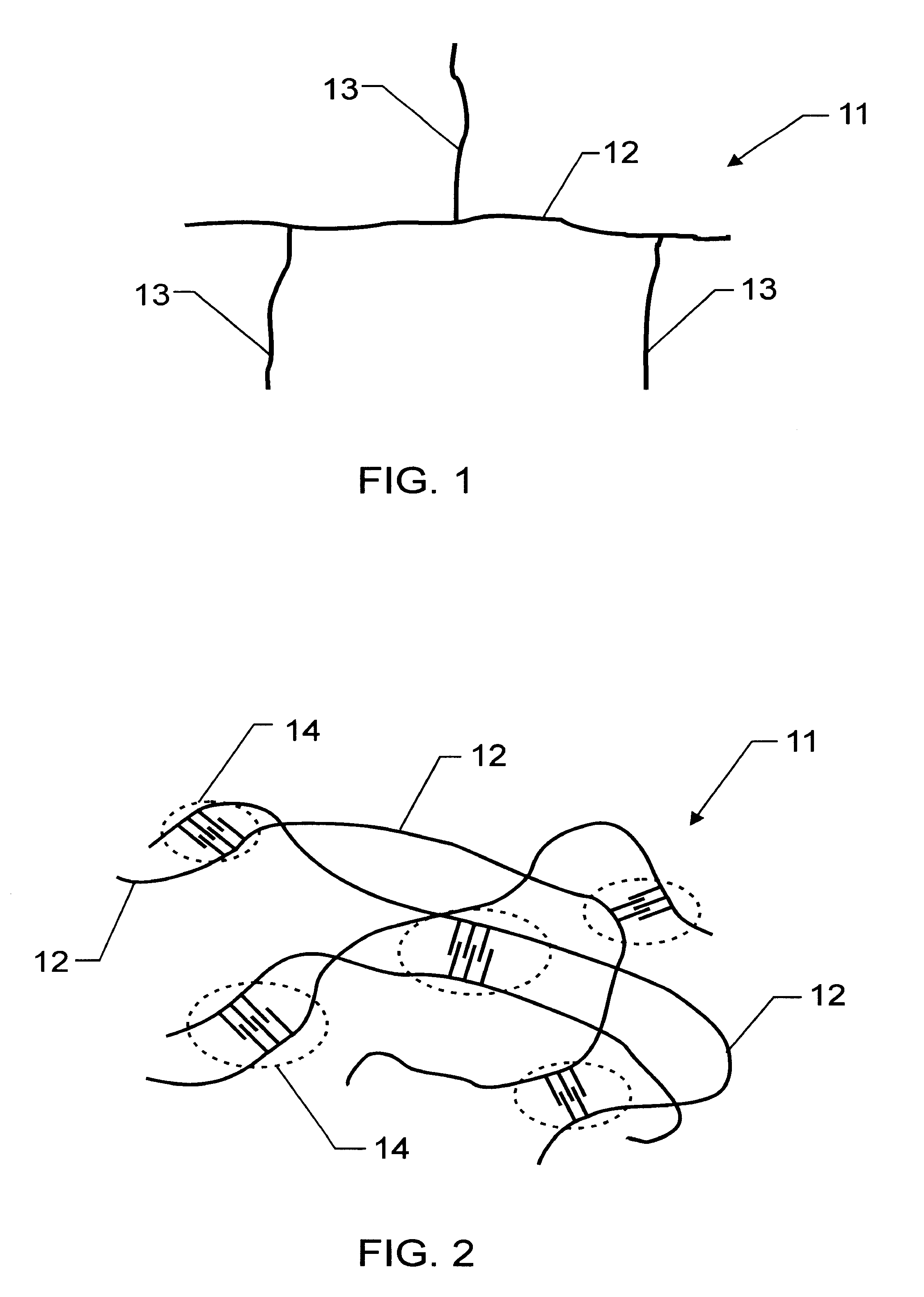
FIG. 1 is a schematic representation of the molecular structure of a graft elastomer employed in the present invention;

FIG. 2 is a schematic representation of the morphology of a graft elastomer employed in the present invention;

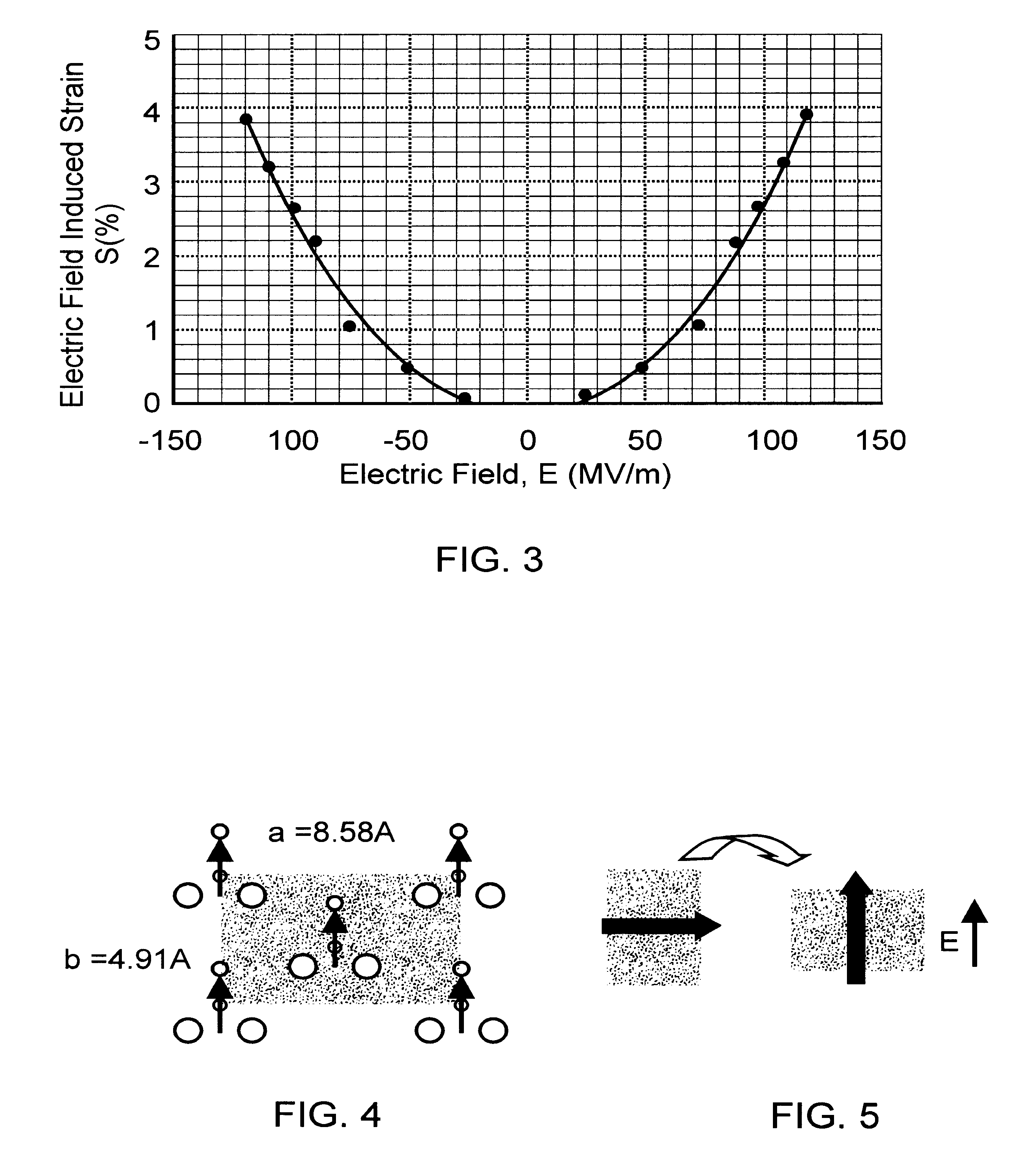
FIG. 3 is a graph showing the relationship between electric field induced strain and applied electric field for an electrostrictive graft elastomer according to the present invention;

FIG. 4 is a schematic representation of a polar crystal phase unit cell in a graft elastomer employed in the present invention;

FIG. 5 schematically depicts reorientation of the polar crystal phase unit cell of FIG. 4 under an applied electric field;

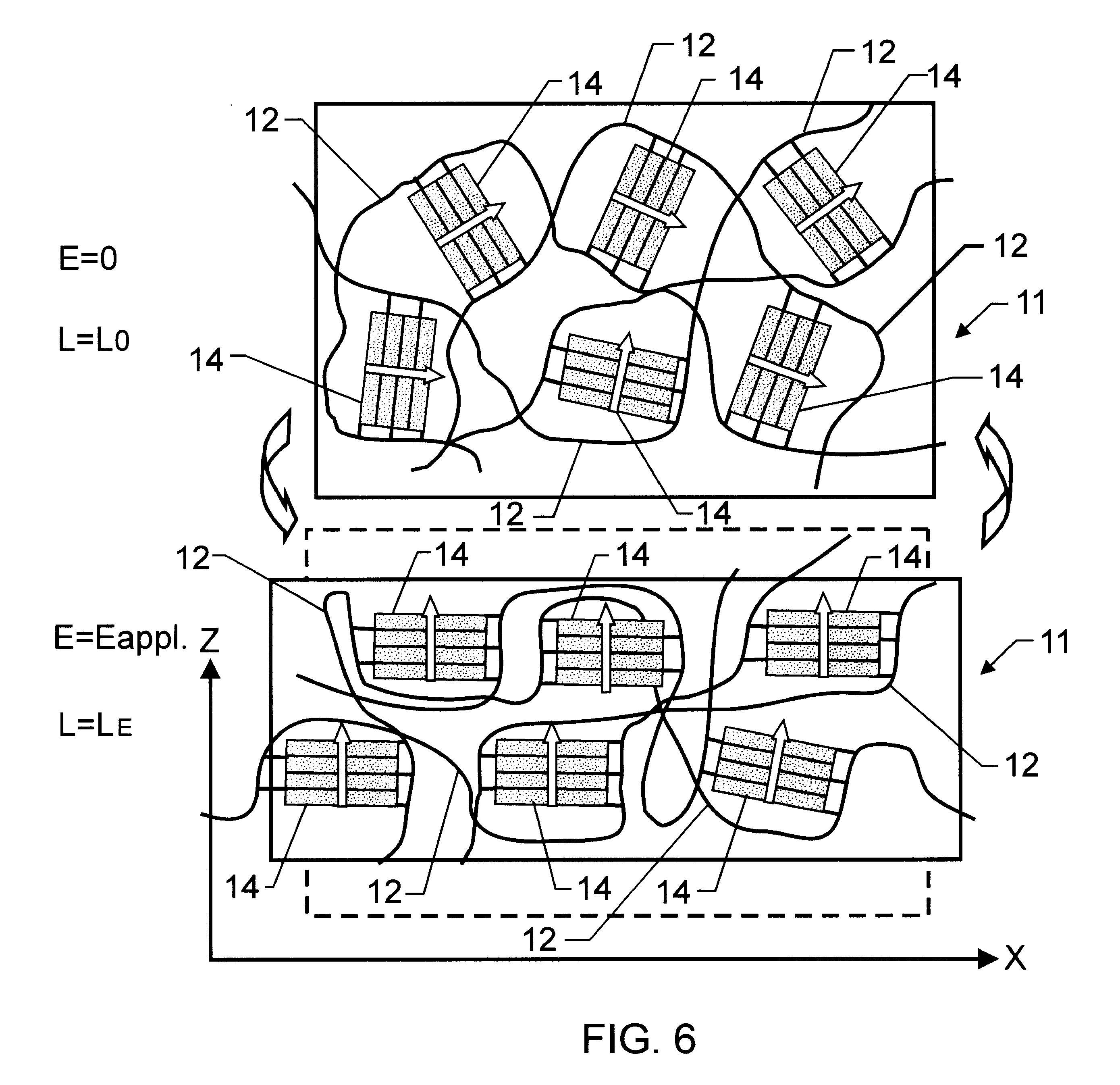
FIG. 6 schematically depicts rotation and reorientation of polar crystal phases in a graft elastomer from an originally randomly distributed configuration to a substantial polar alignment when an electric field is applied; and

FIG. 7 schematically depicts rotation and ...


PUM

PropertyMeasurementUnit
Polarityaaaaaaaaaa
Flexibilityaaaaaaaaaa
Molecular weightaaaaaaaaaa

Abstract

An electrostrictive graft elastomer has a backbone molecule which is a non-crystallizable, flexible macromolecular chain and a grafted polymer forming polar graft moieties with backbone molecules. The polar graft moieties have been rotated by an applied electric field, e.g., into substantial polar alignment. The rotation is sustained until the electric field is removed. In another embodiment, a process for producing strain in an elastomer includes: (a) providing a graft elastomer having a backbone molecule which is a non-crystallizable, flexible macromolecular chain and a grafted polymer forming polar graft moieties with backbone molecules; and (b) applying an electric field to the graft elastomer to rotate the polar graft moieties, e.g., into substantial polar alignment.

Description

1. Field of the InventionThis invention relates to graft elastomers which are electrostrictive. It relates also to a process for producing strain in elastomers.2. Description of the Related ArtElectromechanical coupling effects such as piezoelectricity and electrostriction have been utilized in a number of transducer and actuator technologies. Piezoelectric polymers and ceramics have been the typical candidates for actuation mechanisms. However, piezoelectric polymers such as poly(vinylidene fluoride) provide very low strains, while the ceramics are undesirably heavy and brittle, and provide low strains. To be sure, acceptable strains are now provided by electrostrictive polyurethanes and silicones. However, these polymeric materials have very low moduli, and consequently possess very little actuation authority.Fluorine-containing graft copolymers have been known for some time. For example, U.S. Pat. Nos. 4,472,557 and 4,910,258 disclose the graft copolymerization of fluorine-contai...

Claims


Application Information

Patent Timeline
IPC IPC(8): C08F291/00C08F283/00C08F259/00C08F255/10C08F255/00C08F265/08C08F259/08C08F283/12C08F273/00C08F265/00H01L41/18H01L41/09H01L41/00H01Q15/14H01L41/193H01L41/053
CPCC08F255/10C08F259/00C08F259/08C08F265/08C08F273/00C08F283/12C08F291/00H01L41/193H01Q15/147C08F283/006H01L41/0973H01L41/0926H10N30/204H10N30/2047H10N30/857
Inventor SU, JIHARRISON, JOYCELYN S.ST. CLAIR, TERRY L.
Owner NASA
Learn More