Pluggable module and receptacle

a technology of receptacle and module, applied in the direction of coupling protective earth/shielding arrangement, coupling device connection, contact member penetrating/cutting insulation/cable strand, etc., can solve the problems of increasing the cost of the system comprising such modules, adding cost to the modules, and affecting the heat sensitive components within the modules. , to achieve the effect of effectively shielding emi emissions, eliminating leakage, and facilitating miniaturization and high operating frequency

Inactive Publication Date: 2003-02-11
TE CONNECTIVITY CORP
View PDF8 Cites 204 Cited by
  • Summary
  • Abstract
  • Description
  • Claims
  • Application Information

AI Technical Summary

Benefits of technology

The present invention provides a pluggable module and receptacle system that facilitates miniaturization and high operating frequencies by effectively shielding EMI emissions to eliminate leaks and conduct EMI to ground, and by synergistically using components to eliminate conventional discrete mechanisms and their attendant bulk.
EMI shielding is achieved by implementing one or more features that serve to minimize gaps through which EMI can escape, and / or to enhance grounding of the receptacle. One such feature is a receptacle housing in which all of its sides except the front comprise conductive walls for blocking EMI. This way, when the receptacle is mounted within a host system and is exposed to the host system's internal EMI, all of the housing sides exposed to the EMI, including the back and the bottom, are conductive and thus suitable for conducting the EMI to ground. Preferably, the housing is electrically connected to ground through a number of elongated members. Another feature for minimizing gaps through which EMI can escape is the use of containment members. Containment members extend downward from the receptacle, preferably between elongated members, and essentially form a picket fence along with the elongated members to prevent EMI emissions.
In addition to minimizing gaps through which EMI can escape, the module and receptacle system of the present invention is extremely well suited for conducting EMI to ground. This grounding is achieved principally by grounding contacts on the front end of the module and grounding tabs around the front opening on the receptacle. This way, the grounding contacts provide a grounding path from the module to the receptacle and the grounding tabs, in turn, provide a grounding path from the receptacle to the host chassis. Preferably, the grounding tabs are cut from the receptacle housing walls and elongated such that the grounding tabs are longer than the respective section of the wall from which each grounding tab was derived. Such a configuration prevents the grounding tabs from being deflected into the receptacle cavity. This arrangement is particularly preferable in small form factor configurations in which there is no room in the receptacle cavity to accommodate anything other than the module. To enhance the grounding of the module to the receptacle while the module is being inserted therein, the receptacle housing defines rows of ventilation holes, which, in turn, define uninterrupted ground paths therebetween. By spacing the grounding contacts on the module to correspond to the spacing of the grounding paths on the receptacle, the grounding contacts will slide along the grounding paths during insertion and withdrawal of the module from the receptacle, thereby ensuring that the module is continuously grounded during the insertion and withdrawal. Further enhancements to grounding include a latch which serves not only to retain the module within the receptacle, but also to provide a grounding path from the front of the module to the front of the receptacle and to provide an extra picket in the EMI fence as mentioned above.
The module and receptacle system of the present invention also employs components of the receptacle synergistically to avoid separate mechanisms and components which add bulk and cost to the system. For example, rather than using a conventional connector to effect connection of the module to the receptacle connector, a card edge connection configuration is used. Additionally, the ejection mechanism uses a resilient back portion of the receptacle to urge the module out once the latch is released. The more efficient use of components within the module and receptacle provide for the elimination of other components and thus a general reduction in the system's bulk. This naturally facilitates miniaturization which, as mentioned above, is an ever-present objective in module design.

Problems solved by technology

Although solder reflow is an effective technique for electrically connecting a module to a circuit board, the heat required to achieve reflow tends to be detrimental to heat sensitive components within the module, such as plastic optical components which tend to warp or otherwise distort at high temperatures.
Furthermore, to ensure that modules are capable of withstanding the environmental conditions associated with reflow soldering, the industry utilizes high temperature materials that add cost to the modules.
The need for hand soldering, however, dramatically increases the cost of system comprising such modules.
Aside from the problems associated with soldering the module to the circuit board, there is the added inconvenience that, if a single module fails on a circuit board, which may support many such modules, the entire circuit board must be removed for service.
Although these conventional pluggable designs have been used successfully in the past, they tend to be unsuitable for miniaturization which is an ever-constant objective in the industry.
Conventional pluggable module configurations, however, cannot meet these parameters.
Miniaturizing a module while maintaining or even increasing its operating speed, presents a number of design problems particularly in applications in which data transmission rates are high, e.g., in the range of 1-10 Gbs (Gigabits / second).
Providing space for spring-loaded doors and spring clips on the receptacle tends to be problematic if not impossible in miniaturized configurations.
Additionally, the small size presents problems in dissipating heat from the module and incorporating traditional mechanisms for ejecting and retaining the module and for electrically connecting the module to the host circuit board.

Method used


Image

  • Pluggable module and receptacle
  • Pluggable module and receptacle
  • Pluggable module and receptacle

Examples


Embodiment Construction

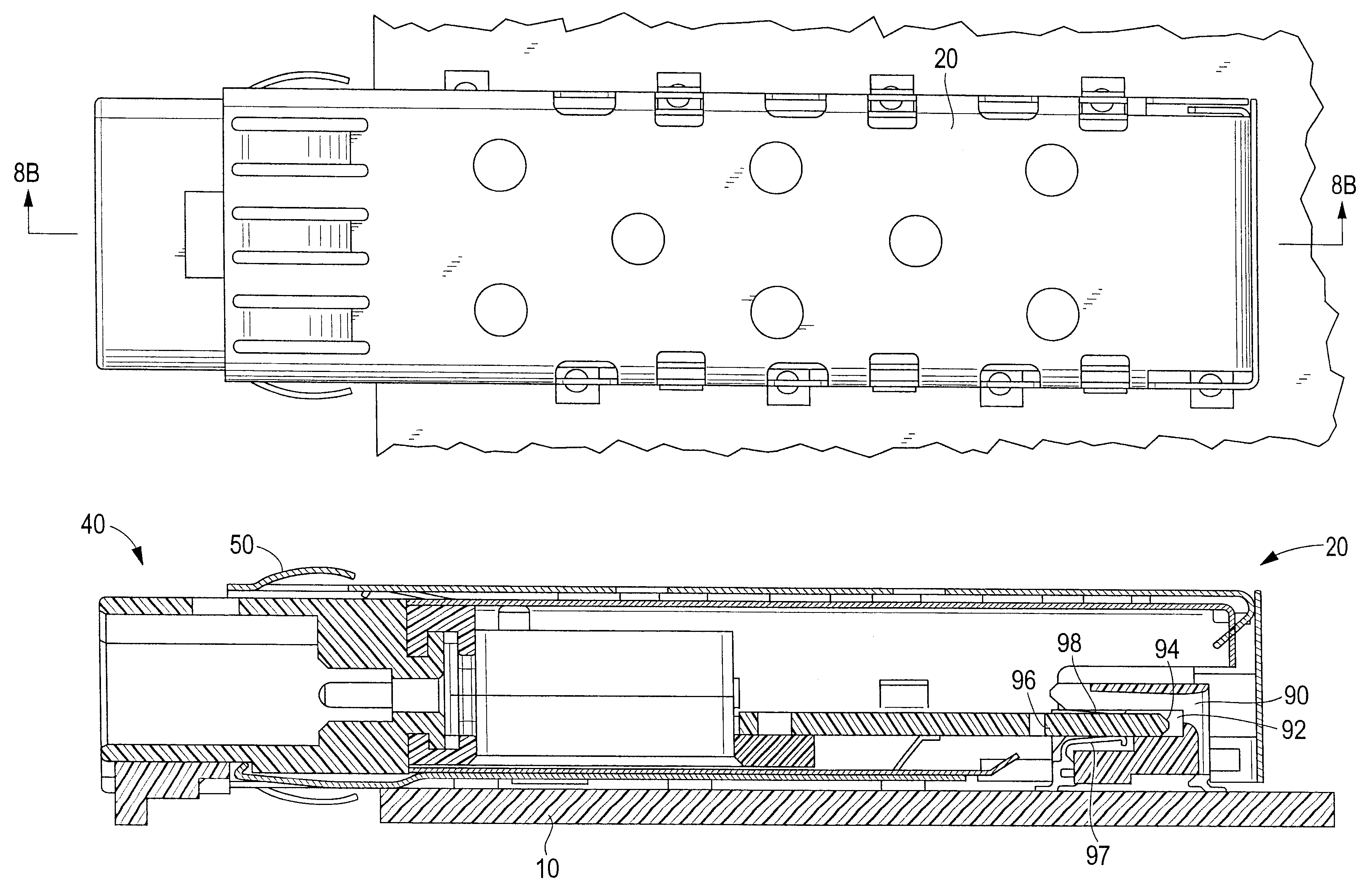
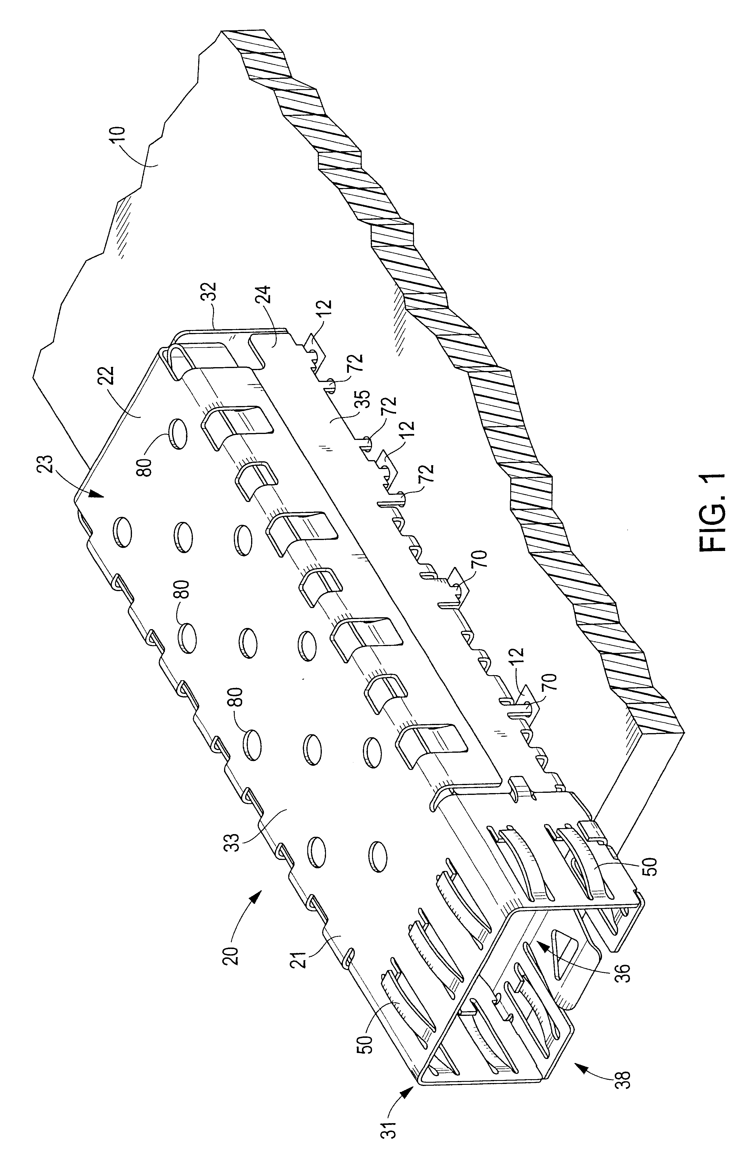
The present invention provides a robust module and receptacle system which is suitable for miniaturization and which provides adequate EMI shielding and ventilation while facilitating easy connection / disconnection to a mating connector. As shown in FIG. 1, a receptacle 20 of the present invention is mounted to a host circuit board 10. The host circuit board is mounted in a host system such as a router or computer. The host system typically comprises a conductive chassis (not shown) having a bezel through which the receptacle is mounted such that the receptacle is electrically connected to the bezel. The host system typically has other components mounted to its circuit board which generate EMI that would escape through the bezel if not for the receptacle system of the present invention.

The module 40 of the present invention is shown in FIG. 9 and is configured to be inserted in the receptacle 20. In general, the module and receptacle system may be used in any application requiring an...


PUM


Abstract

A receptacle for a pluggable module includes a housing having a front, a back wall, a top wall, a bottom wall, and side walls and defining a cavity for receiving a module. The bottom wall has a bottom opening to receive a receptacle connector, and the front has a front opening to receive the module. The walls of the housing are made from a conductive material. A plurality of elongated members extend down from the housing past the bottom wall. The elongated members are adapted for electrical connection to a host circuit board such that the walls of the housing are electrically connected to the host circuit board.

Description

The present invention relates generally to electronic connector systems and, more specifically, to low-profile connector systems for pluggable electronic modules, such as transceiver modules for high speed fiber optical and copper communications.BACKGROUND OF INVENTIONHistorically, electrical and opto-electric modules have been connected to printed circuit boards with solder pins. Conventional approaches for soldering the pins to the circuit board include reflow soldering and hand soldering. Although solder reflow is an effective technique for electrically connecting a module to a circuit board, the heat required to achieve reflow tends to be detrimental to heat sensitive components within the module, such as plastic optical components which tend to warp or otherwise distort at high temperatures. Furthermore, to ensure that modules are capable of withstanding the environmental conditions associated with reflow soldering, the industry utilizes high temperature materials that add cost...

Claims


Application Information

Patent Timeline
Patent Type & Authority Patents(United States)
IPC IPC(8): H01R13/658H05K9/00
CPCH05K9/0058H01R13/65802H01R13/6582H01R13/6594
Inventor FLICKINGER, STEVEN L.HERB, WILLIAM L.VEITH, WILLIAM E.KERLIN, HAROLD W.BRIGHT, EDWARD J.KEMMICK, DENNIS L.
Owner TE CONNECTIVITY CORP
Why Eureka
Try Eureka