Method for generating a short-pulsed microwave and an equipment for generating a short-pulsed microwave

a technology of short-pulsed microwave and equipment, which is applied in pulse technique, active medium material, instruments, etc., can solve the problem of difficult to obtain a short-pulsed microwave having a pulse of not more than 10 nsec, and achieve the effect of obtaining a microwave with a short pulse extremely easily

Inactive Publication Date: 2003-02-11
UTSUNOMIYA UNIV
View PDF12 Cites 5 Cited by
  • Summary
  • Abstract
  • Description
  • Claims
  • Application Information

AI Technical Summary

Benefits of technology

It is an object of the present invention to provide a new method for generating a short-pulsed microwave and a new equipment for generating a short-pulsed microwave which are able to obtain a microwave having a short pulse extremely easily.

Problems solved by technology

Thus, as a matter of fact, it is difficult to obtain a short-pulsed microwave having a pulse of not more than around 10 nsec.

Method used


Image

  • Method for generating a short-pulsed microwave and an equipment for generating a short-pulsed microwave
  • Method for generating a short-pulsed microwave and an equipment for generating a short-pulsed microwave
  • Method for generating a short-pulsed microwave and an equipment for generating a short-pulsed microwave

Examples


example 1

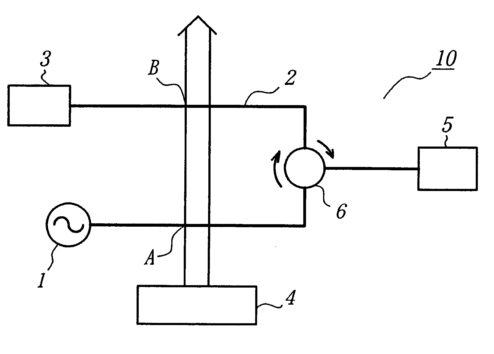
In this example, by using the short-pulsed microwave-generating equipment 10 shown in FIG. 1, a microwave was short-pulsed.

As the microwave oscillator 1, a gun oscillator (output power: 5 mW, frequency: 9 GHz) was used. As the waveguided tube, a WRJ 10 was used. As the laser source 4, a fourth harmonic wave (wavelength: 266 nm) of a YAG laser (output power: 160 mJ, pulse width: 6 nsec) was employed. Commercially available ones are employed for the dummy load 3, the microwave detector 5 and the isolator 6.

After tetrakisdimethylaminoethylene (TMAE) was charged into the waveguided tube 2 up to a pressure of 10 mTorr, a laser having a intensity of 0.5 J / cm.sup.2 from the laser source 4 was irradiated to the tube 2 and thereby, the TMAE was partially made plasma.

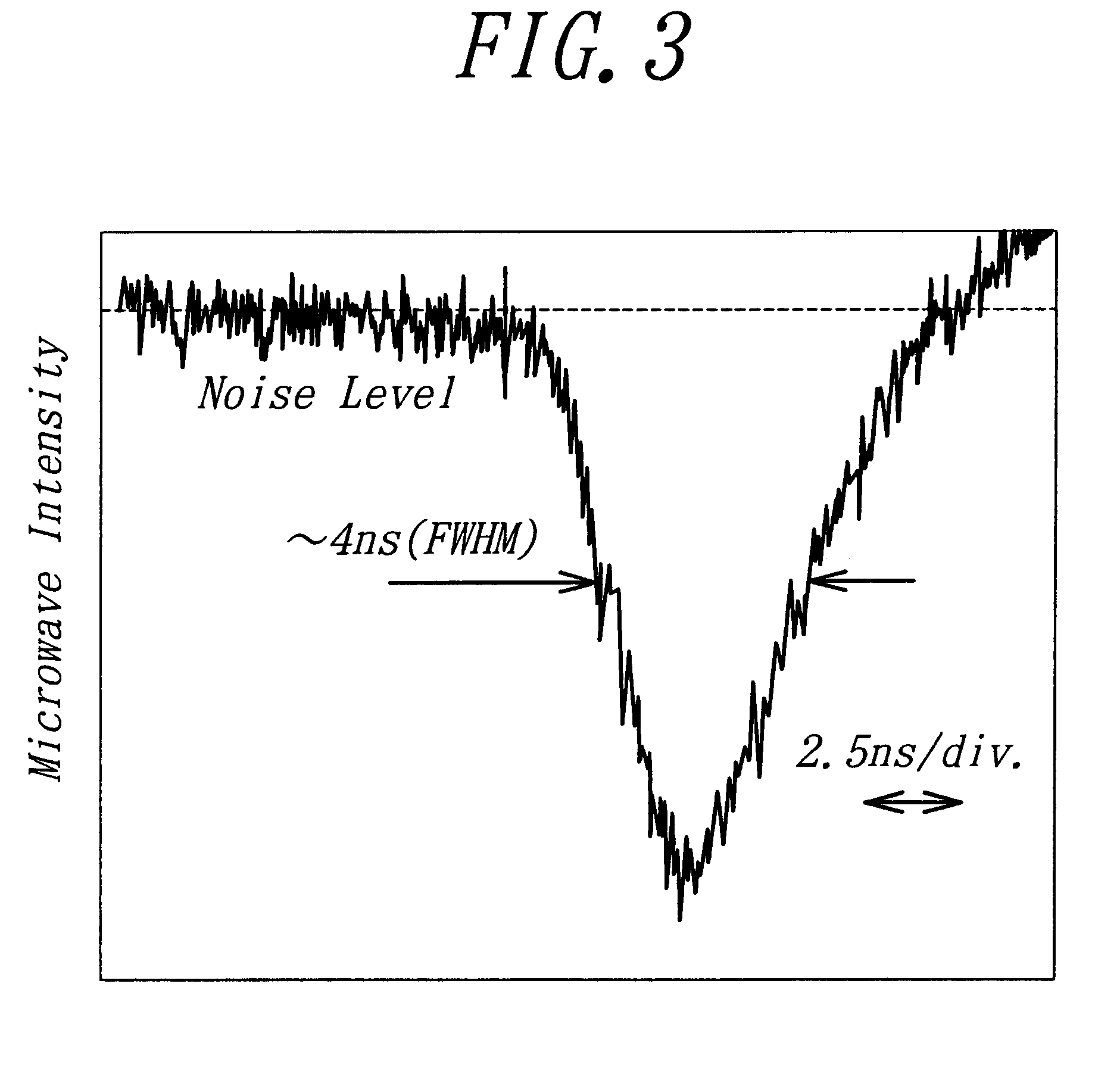
Thereafter, when the wave profile of the microwave was investigated by the microwave detector 5, it showed the result shown in FIG. 3. The result gives the microwave a pulse width of about 4 nsec. Thus, it is figured out that the...

example 2

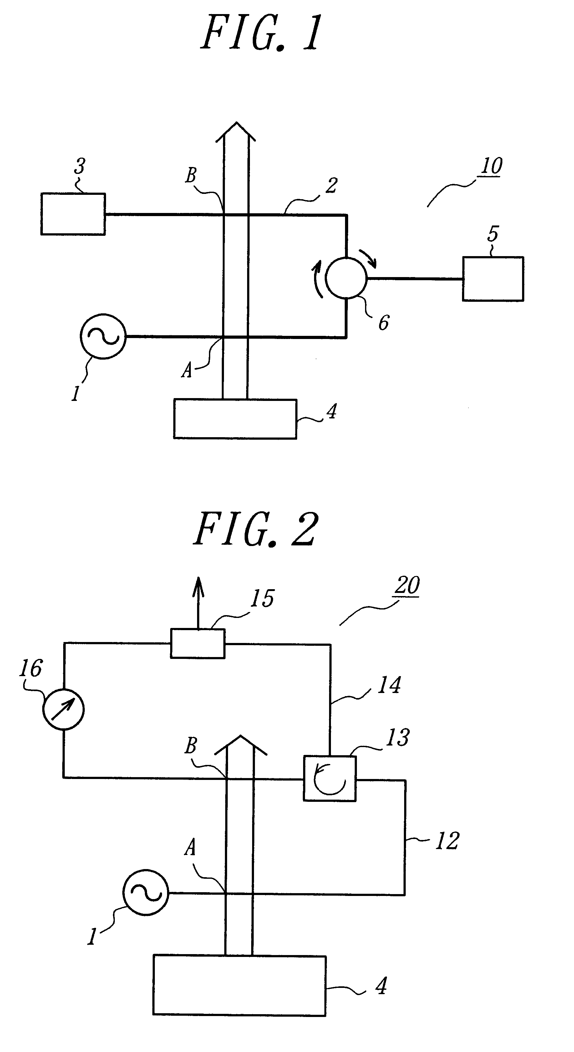
In this example, by using the short-pulsed microwave-generating equipment 20 shown in FIG. 2, a microwave was short-pulsed and the output power of the short-pulsed microwave was increased.

As the microwave oscillator 1, the laser source 4, the first and the second waveguided tubes 12, 14, the same ones as in Example 1 were employed. Moreover, Commercially available ones are employed for the circulator 13, the magic tee 15 and the phase-shifter 16.

TMAE was introduced into the first and the second waveguided tubes 12 and 14 by the same manner as in Example 1 and thereafter, an oscillated microwave was propagated in the first tube 12 and the second tube 14. Then, a laser was irradiated to the first tube 12 and the second tube 14 by the same manner as in Example 1.

When the wave profile of the microwave was investigated by the magic tee 15, it showed the result shown in FIG. 4. That is, the microwave is divided into the two microwaves having a pulse 1 (pulse width: 4 nsec) and a pulse 2 (...


PUM

PropertyMeasurementUnit
pressureaaaaaaaaaa
wavelengthaaaaaaaaaa
pressureaaaaaaaaaa

Abstract

A continuous or a long-pulsed microwave oscillated from a microwave oscillator 1 is propagated in a waveguided tube 2 in which a given gas is charged. Subsequently, by irradiating a laser having a given intensity from a laser source 4 to the points, A and B in the tube 2, the given gas is partially made plasma. Just then, the microwave can not travel beyond the plasma-part of the given gas and reflects thereat. Accordingly, the microwave is divided at the plasma-part and thereby, a short-pulsed microwave can be obtained.

Description

1) Field of the InventionThis invention relates a method for generating a short-pulsed microwave and an equipment for generating a short-pulsed microwave, more particular a method for generating a short-pulsed microwave and an equipment for generating a short-pulsed microwave preferably usable in a microwave-related field such as a high frequency-accelerator and a high frequency-radar.2) Description of the Prior ArtRecently, in a microwave-related field such as a high frequency accelerator and a high frequency-radar, a microwave is required to be short-pulsed in view of high output power.In the past, the short-pulsing was carried out through directly short-pulsing a voltage to apply a microwave-oscillation tube and an electron beam to oscillate a microwave.In the case of short-pulsing the voltage to apply the microwave oscillation tube as above-mentioned, however, a high voltage output-circuit is required to be make low-inductance. Moreover, in the case of short-pulsing the electron...

Claims


Application Information

Patent Timeline
Patent Type & Authority Patents(United States)
IPC IPC(8): H03K5/06H03K5/04H01S3/16C07C211/22G01S7/282H01P3/12H03B9/14H03K3/42
CPCH03K5/06
Inventor YUGAMI, NOBORUNISHIDA, YASUSHIITO, HIROAKI
Owner UTSUNOMIYA UNIV
Why Eureka
Try Eureka