Microsensor having a sensor device connected to an integrated circuit by a solder joint

a sensor device and integrated circuit technology, applied in the field of microsensors, can solve problems such as reducing sensitivity

Inactive Publication Date: 2003-02-18
AUSTRIA MIKRO SYST INT
View PDF8 Cites 21 Cited by
  • Summary
  • Abstract
  • Description
  • Claims
  • Application Information

AI Technical Summary

Problems solved by technology

Due to the relatively long lines between the components to be joined, there are relatively high parasitic capacities of bonded p

Method used


Image

  • Microsensor having a sensor device connected to an integrated circuit by a solder joint
  • Microsensor having a sensor device connected to an integrated circuit by a solder joint

Examples


Embodiment Construction

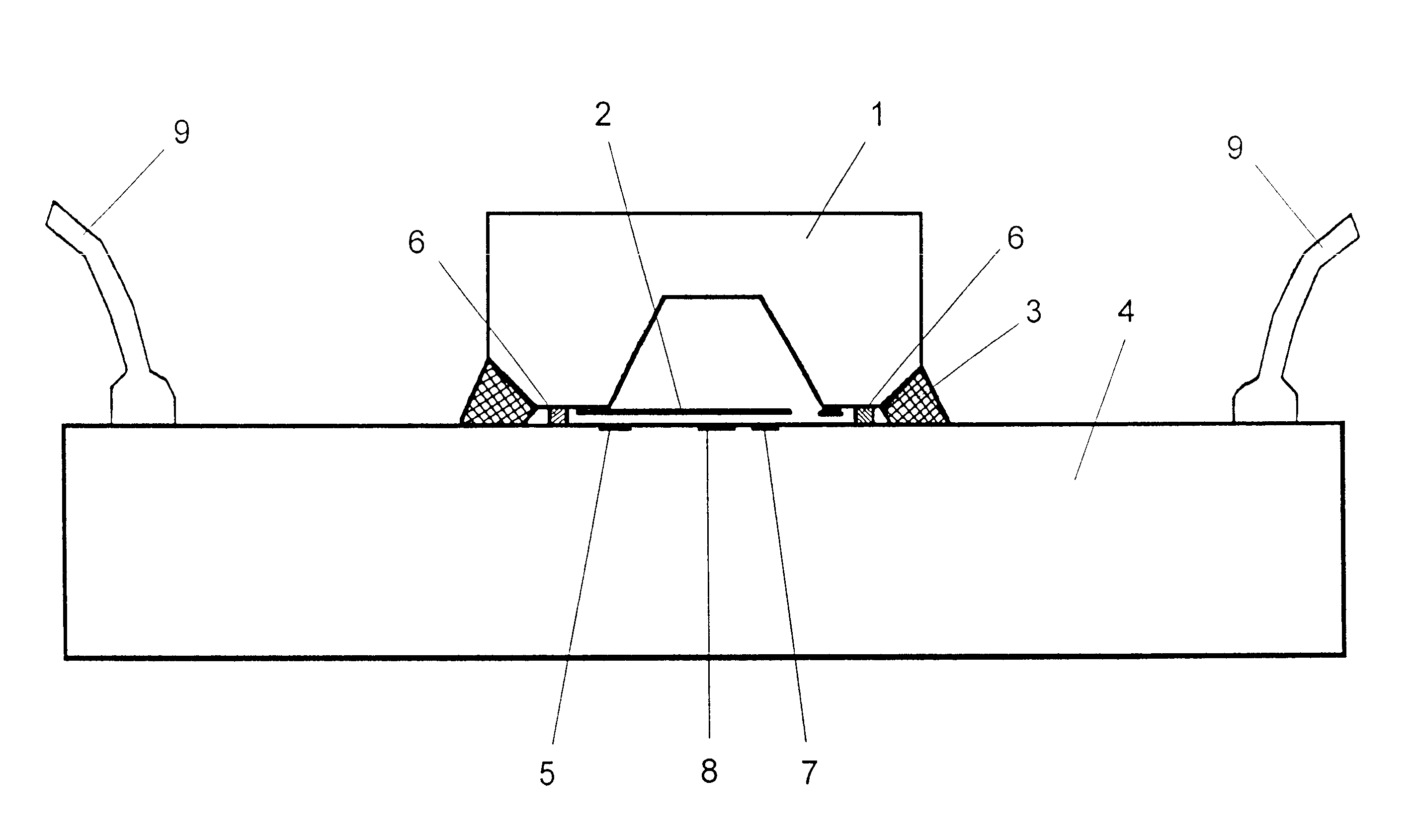
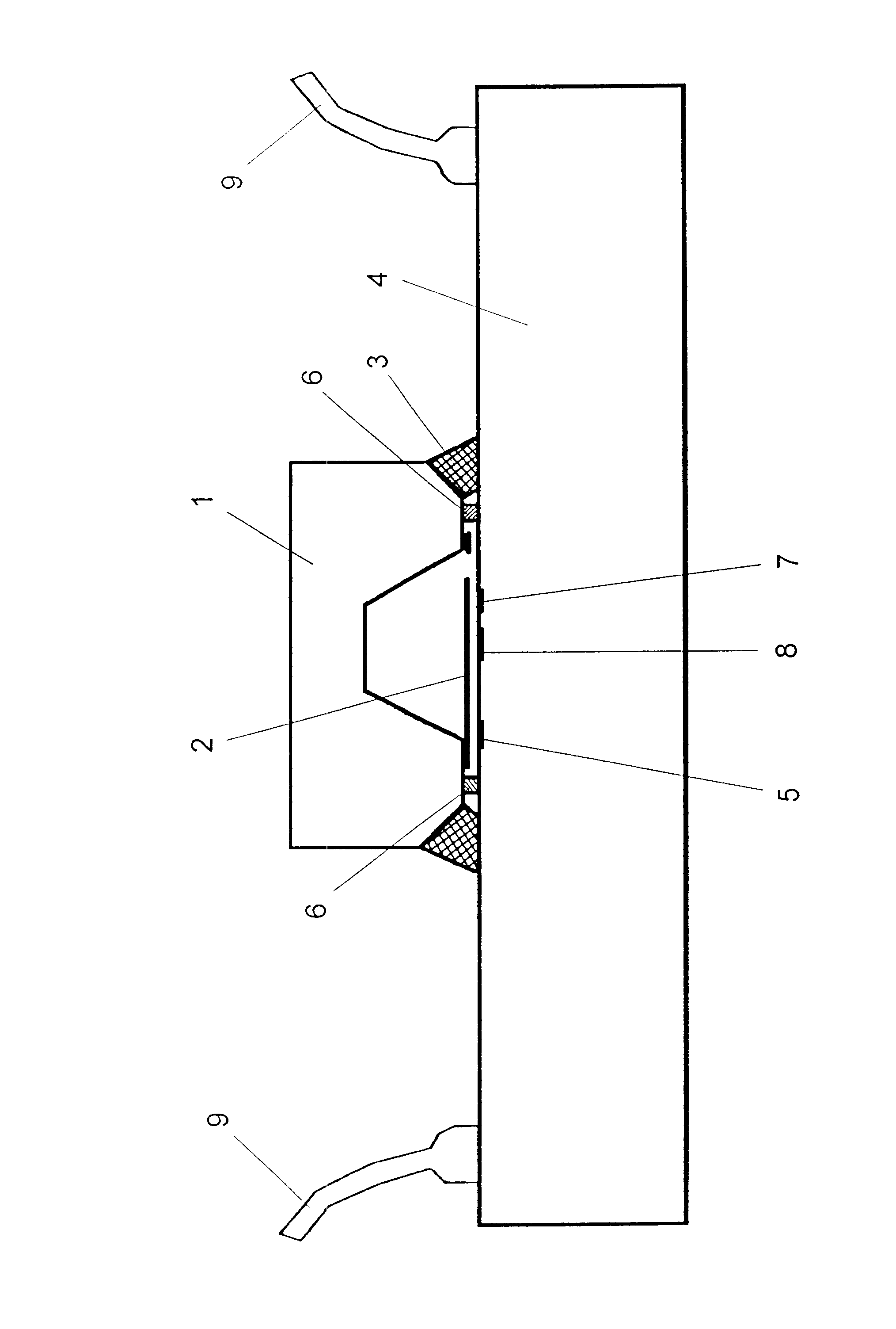
In the FIGURE, a micro-electromechanical sensor element (1) consisting of electrically conductive silicon is shown. A flexural bar (2) is formed by back-etching, which in turn forms a capacitor plate, which in turn is connected to an IC (4) in an electrically conductive manner by a circulating soldered joint (3). Thereby, the integrated circuit (IC) (4) has a contact surface (5) on the surface facing the capacitor plate (2) of the micro-electromechanical sensor element (1), which together with the electrically conductive plate of the flexural bar (2) forms a reference capacitor, since the gap between this surface and the flexural bar (2) is subject to only minor changes, even on articulation of the flexural bar (2). Thereby, the gap is defined primarily by the spacer (6).

In case of acceleration, tilting or rotation, the dielectric gap between the flexural bar (2) and the electrically conductive plates of the IC underneath changes, whereby the capacitor plate of the measuring sensor ...


PUM


Abstract

In a microsensor with a micro-electromechanical sensor element and an integrated circuit for measuring, calibration and compensation electronics, whereby the sensor is connected electrically to the integrated circuit (IC), the micro-electromechanical sensor element is arranged directly on the integrated circuit with accurate positioning, and is connected with electric conductivity via a circulating soldered joint.

Description

1. Field of the InventionThe invention refers to a microsensor with a micro-electromechanical sensor element and an integrated circuit for measuring, calibration and compensation electronics, whereby the sensor element has an electric connection to the integrated circuit (IC).2. Prior ArtMicrosensors of the type mentioned above are used for a wide range of applications. In addition to proximity switches and acceleration sensors, for example semiconductor pressure sensors have already become known, in which a sensor element and a carrier of different materials are joined by soldering. As a sensor element for such pressure sensors, silicon membranes have already been suggested, whereby various degrees of compression can result due to the different e-modules of the material used. Pressure leads to deformation, and use of the piezoresistant effect of resistors diffused into silicon membranes for measuring pressures up to several 100 bar is already known. In the known microsensors, the e...

Claims


Application Information

Patent Timeline
IPC IPC(8): B81B7/00G01P1/02G01P15/13G01P1/00G01P15/125H01L29/06
CPCB81B7/0041B81B7/007B81C3/002G01P1/023G01P15/125G01P15/131B81C2203/019H01L2224/48463H01L29/0657B81C2203/058G01P2015/0828
Inventor BRANDL, MANFRED
Owner AUSTRIA MIKRO SYST INT
Why Eureka
Try Eureka