Plasma density measuring method and apparatus, and plasma processing system using the same

a density measurement and plasma technology, applied in the field of plasma density measurement method and apparatus, and plasma processing system, can solve the problems of plasma disturbance, large measuring apparatus, and degradation of processing uniformity,

Inactive Publication Date: 2003-04-01
CANON KK
View PDF5 Cites 17 Cited by
  • Summary
  • Abstract
  • Description
  • Claims
  • Application Information

AI Technical Summary

Problems solved by technology

This raises various inconveniences such as etching of the probe by a corrosive gas plasma, deposition of an insulating film on the probe surface due to a depositing gas plasma, introduction of metal contamination into a processing chamber, and disturbance of the plasma 305, for example.
However, the problem of plasma disturbance is still unsolved.
Particularly, where probe inserted (in-situ) monitoring of a plasma for use in a production machine is to be executed, the insertion of the probe directly causes degradation of the uniformity of processing, and therefore, it is impractical.
However, the measuring apparatus becomes very large.
Further, the adjustment of the microwave path is not easy.
For these reasons, practically it is very difficult to incorporate this measuring unit into a production machine.
As described above, with conventional plasma density measuring methods using probes, at least the problem of plasma disturbance inevitably occurs.
Further, with conventional plasma density measuring methods using microwave interference, while the problem of disturbance can be avoided because it is non-contact to the plasma, there still remain inconveniences such as that the measuring system is very large.
It is therefore practically very difficult to incorporate the unit into a production machine.

Method used


Image

  • Plasma density measuring method and apparatus, and plasma processing system using the same
  • Plasma density measuring method and apparatus, and plasma processing system using the same
  • Plasma density measuring method and apparatus, and plasma processing system using the same

Examples


example 2

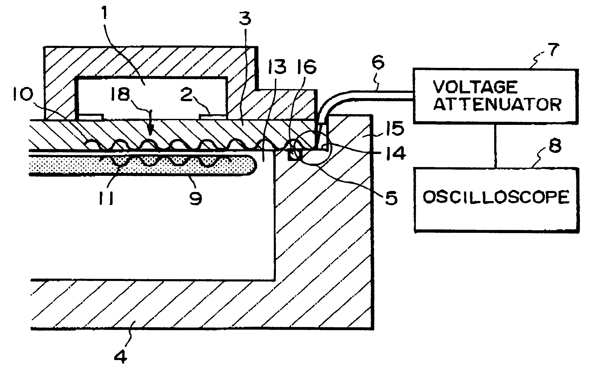
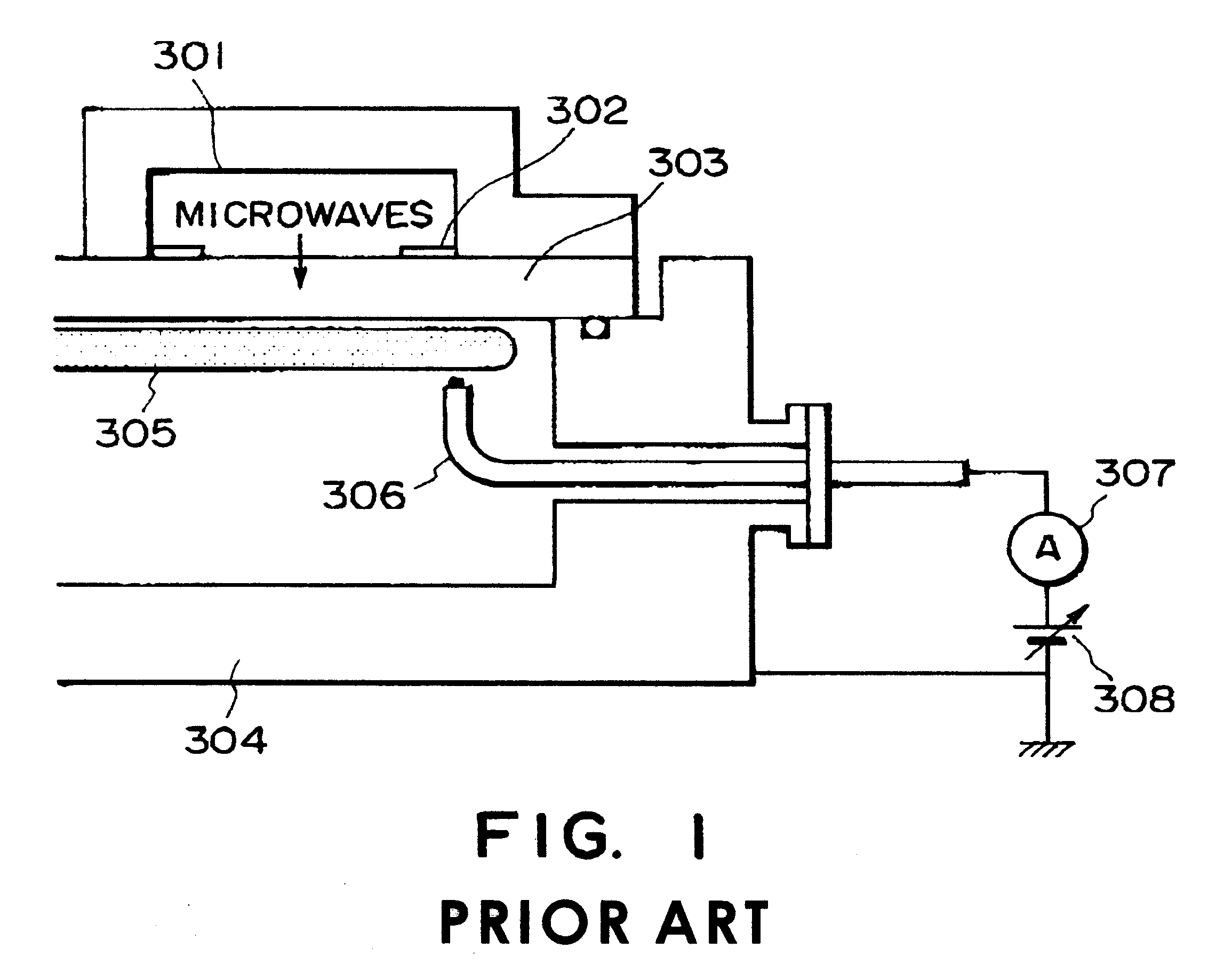
A second example of the present invention will be described with reference to a case where the plasma density in a surface wave interference type plasma processing is the subject of measurement and where the uniformness of a plasma in a circumferential direction is to be specifically measured. The structure of a surface wave plasma processing apparatus of this embodiment may be similar to that shown in FIG. 2. As regards a dielectric member 3, a quartz material of disk-like shape having a diameter 280 mm and a thickness 14 mm was used. Slot antennas 2 comprised six slots disposed radially with 60 deg. intervals. Surface wave detecting antennas 5 were provided at the atmosphere side (outside an O-ring 16) of the circumferential portion of the dielectric member 3, and they were connected to a voltage attenuator 7 of 1 / 1000, through cables 6. The output of the attenuator was connected to an oscilloscope 8. As regards the antennas 5, six antennas were provided along a circumferential di...

example 3

A third example of the present invention will be explained with reference to a case where a plasma density in a surface wave interference type plasma processing apparatus is the subject of measurement and where a change of plasma density with respect to time is to be specifically measured. The structure of a surface wave plasma processing apparatus in this embodiment may be similar to that shown in FIG. 2. As regards a dielectric member 3, a quartz material of disk-like shape having a diameter 280 mm and a thickness 14 mm was used. Slot antennas 2 comprised six slots disposed radially with 60 deg. intervals. Surface wave detecting antennas 5 were provided at the atmosphere side (outside an O-ring 16) of the circumferential portion of the dielectric member 3, and they were connected to a voltage attenuator 7 of 1 / 1000, through cables 6. The output of the attenuator was connected to an oscilloscope 8.

First, an Ar gas of 200 sccm was introduced into the vacuum container 4 having been e...

example 4

In a fourth example, the present invention is applied to a surface wave interference type plasma processing apparatus to measure a plasma density so that it is fed back to the microwave power. The structure of a surface wave plasma processing apparatus in this embodiment may be similar to that shown in FIG. 6. As regards a dielectric member window, a quartz member having a diameter 280 mm and a thickness 14 mm was used. Slot antennas comprised six slots disposed radially with 60 deg. intervals. Surface wave detecting antennas were provided at the atmosphere side (outside an O-ring) of the circumferential portion of the dielectric member, and they were connected to a peak voltage detecting circuit through a voltage attenuator of 1 / 1000 and cables. The output thereof was then connected to a microwave oscillator control unit. The microwave oscillator control unit had a PID control circuit incorporated therein, to change the microwave output so that the surface wave signal intensity bec...


PUM

PropertyMeasurementUnit
thicknessaaaaaaaaaa
pressureaaaaaaaaaa
pressureaaaaaaaaaa

Abstract

A plasma density measuring method which includes producing a surface wave at an interface between a dielectric member and a plasma, and measuring at least one of a plasma density and a relative change in plasma density, on the basis of the surface wave. A plasma processing system including a container having a window, and for storing therein a gas introduced thereinto, a dielectric member for closing the window of the container, a plasma voltage source for applying a high frequency voltage through the dielectric member to produce a plasma by use of the gas inside the container, wherein a predetermined process is performed by use of the thus produced plasma, a detecting system for detecting an electric field intensity distribution of a surface wave propagated through the dielectric member, and a feedback system for feeding back the result of detection by the detecting system, to determine a processing condition for the process.

Description

FIELD OF THE INVENTION AND RELATED ARTThis invention relates to plasma density measuring method and apparatus for use in an apparatus for producing a plasma by introducing a high frequency electric power through a dielectric member.Conventional plasma density measuring methods are mainly based on inserting a probe into a plasma.As an example, Basics of Plasma Engineering (Akasaki, et al., Sangyo Tosho Shuppan, p207) describes a method of measuring plasma density and temperature by using a Langmuir probe. FIG. 1 shows a plasma density measuring apparatus using a Langmuir probe. In FIG. 1, denoted at 301 is an annular wave guide tube, and denoted at 302 is a slot antenna. Denoted at 303 is a dielectric member, and denoted at 304 is a vacuum container having a window as closed by the dielectric member 303. Denoted at 305 is a plasma, and denoted at 306 is a Langmuir probe. Denoted at 307 is an ammeter, and denoted at 308 is a voltage source. In this Langmuir probe 306, an electric volt...

Claims


Application Information

Patent Timeline
Patent Type & Authority Patents(United States)
IPC IPC(8): G01R19/00H05H1/00H05H1/46
CPCH05H1/0062G01R19/0061
Inventor KITAGAWA, HIDEOSUZUKI, NOBUMASA
Owner CANON KK
Why Eureka
Try Eureka