Suppression of radio frequency interference and impulse noise in communications channels

a technology of radio frequency interference and impulse noise, applied in the direction of line-fault/interference reduction, line balance variation compensation, transmission, etc., can solve the problem that conventional techniques, such as cable balancing, are no longer sufficient to suppress radio frequency or impulse nois

Inactive Publication Date: 2003-04-08
BELL CANADA
View PDF8 Cites 51 Cited by
  • Summary
  • Abstract
  • Description
  • Claims
  • Application Information

AI Technical Summary

Problems solved by technology

In the telephone system, noise may comprise radio frequency interference (RI) produced by commercial radio stations in the vicinity of the communications channel.
Impulse noise may also be caused by technicians working on the subscriber loops, or even by lightning.
With the introduction of digital subscriber loops, especially very high speed digital subscriber loops (VDSL) and asymmetric digital subscriber loops (ADSL), the operating frequency approaches the radio frequency bands and conventional techniques, such as balancing of the

Method used


Image

  • Suppression of radio frequency interference and impulse noise in communications channels
  • Suppression of radio frequency interference and impulse noise in communications channels
  • Suppression of radio frequency interference and impulse noise in communications channels

Examples


Embodiment Construction

)

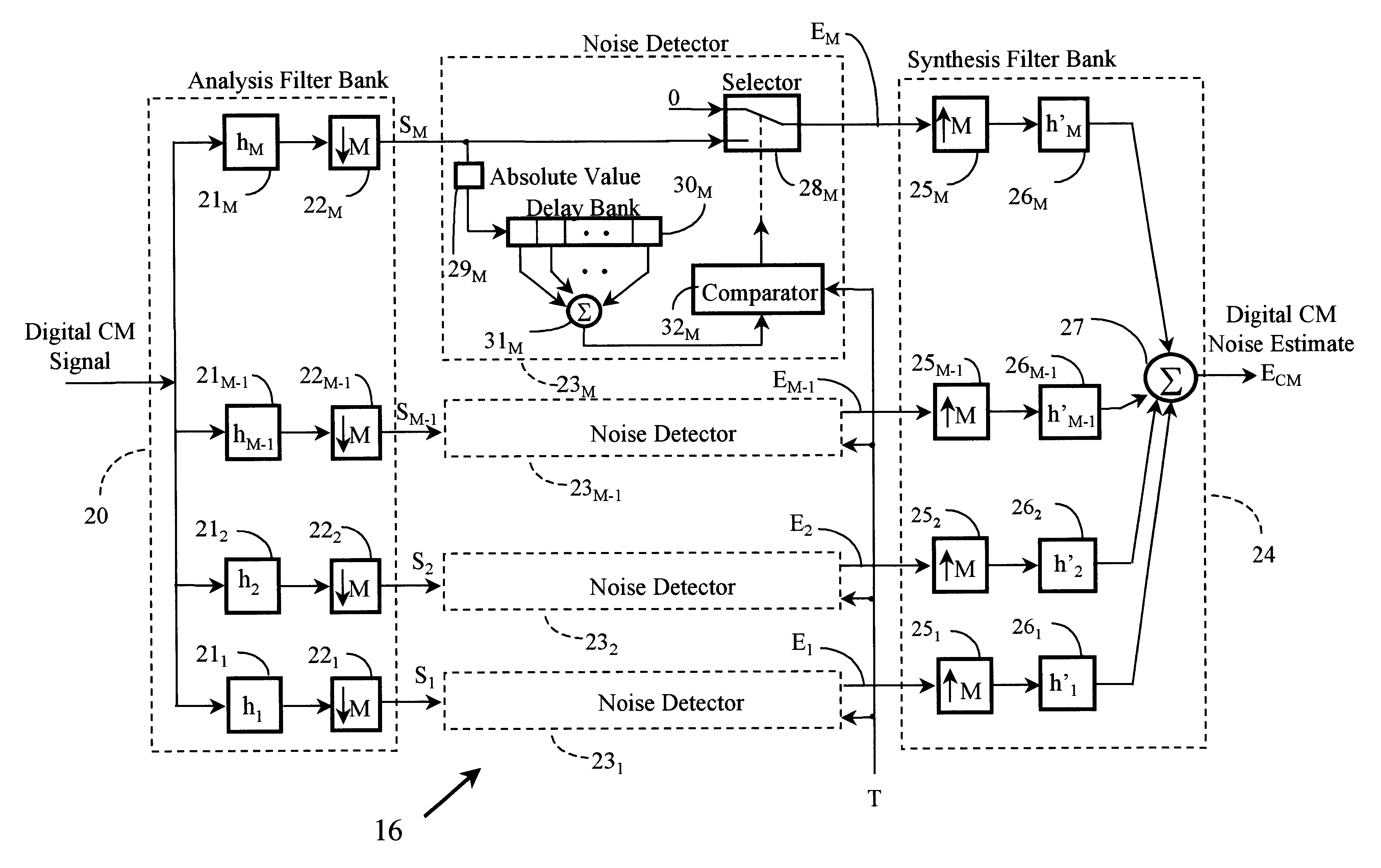
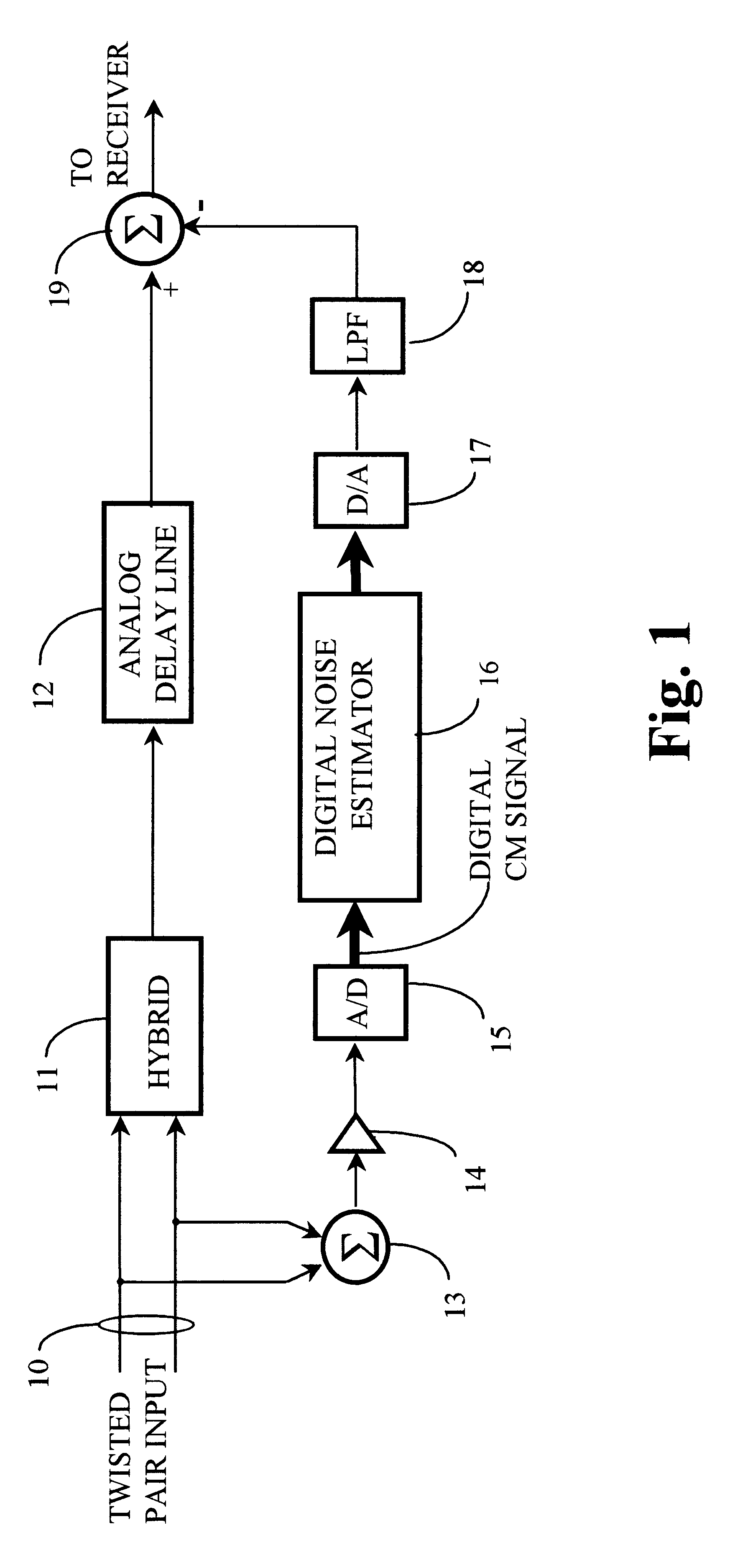
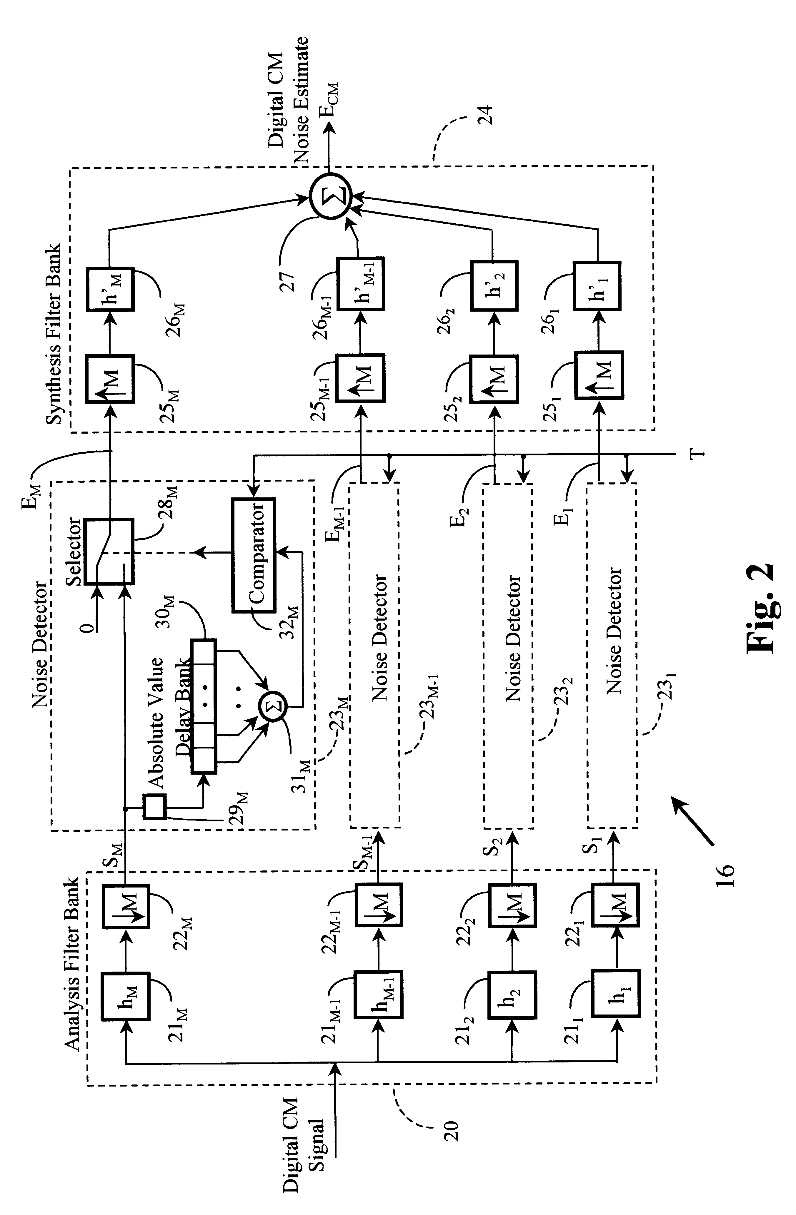
Referring now to FIG. 1, in a noise suppression circuit according to an embodiment of the invention, the TIP and RING wires of a twisted pair subscriber loop 10 are coupled to the respective inputs of a hybrid device in the form of a circuit or transformer 11 and also to respective inputs of a summer 13 which extracts a common mode signal. The output of the hybrid device 11 is coupled by way of an analog delay line 12 to one input of a summer 19, the output of which is coupled to the usual receiver (not shown). The hybrid device 11 converts the signal received from subscriber loop 10 to a differential signal which includes a component corresponding to common mode noise in the received signal.

The common mode signal from summing device 13 is amplified by an amplifier 14 and applied to a noise estimation unit comprising an analog-to-digital converter 15 and a digital noise estimator 16. The amplified common mode noise signal is converted to a digital signal by analog-to-digital conver...


PUM


Abstract

A noise suppression circuit for a communications channel (10) comprises a hybrid device (11) coupled to the channel for providing a differential output signal corresponding to a received signal. A delay unit (12) delays the differential signal by a suitable amount to allow for the generation and subtraction of a noise estimate. A summing device (13) extracts a digital common mode signal from the channel, and a noise estimation unit (16) provides a common mode noise estimate signal in dependence upon a history of the common mode signal over a predetermined period of time and over a plurality of frequency bands. The common mode noise estimate signal is combined subtractively (19) with the delayed differential signal to cancel common mode noise elements of the delayed differential signal. The noise estimation unit may comprise an analysis filter bank (20) for producing a plurality of subband signals (S1-SM), each at a different one of a plurality of different frequencies, a plurality of noise detection circuits (231-23M), each for processing a respective one of the plurality of subband signals to provide a component of the common mode noise estimate signal, and a synthesis filter bank (24) for processing the common mode noise signal components to provide the noise estimate signal.

Description

1. Technical Field ArtThe invention relates to a method and apparatus for reducing noise in signals transmitted via communications channels and is especially, but not exclusively, applicable to the suppression of common mode noise, including radio frequency interference and / or impulse noise, in digital subscriber loops of telecommunications systems. The invention is especially applicable to two-wire or "twisted pair" subscriber loops.2. Background ArtIn the telephone system, noise may comprise radio frequency interference (RI) produced by commercial radio stations in the vicinity of the communications channel. Impulse noise may be caused by a number of phenomena, including switching transients in the central office equipment, or the station apparatus, or from electrical power equipment connected to power lines that run adjacent the telephone subscriber loops. Impulse noise may also be caused by technicians working on the subscriber loops, or even by lightning. Generally, impulse noi...

Claims


Application Information

Patent Timeline
IPC IPC(8): H04L25/08H04L25/10H04B3/02H04B3/30H04B1/10H04L25/02
CPCH04B1/10H04B1/1036H04B3/30H04L25/10H04L25/085H04L25/0274H04L25/0292
Inventor YEAP, TET HIN
Owner BELL CANADA
Why Eureka
Try Eureka