Plasma display panel manufacturing method for manufacturing a plasma display panel with superior picture quality, a manufacturing apparatus and a phosphor ink

a plasma display panel and plasma technology, applied in the manufacture of electrode systems, electrode systems, electric discharge tubes/lamps, etc., can solve the problems of difficult manufacturing of large-screen lcds, increased depth and weight of crt televisions, and inability to meet the production requirements of large-screen televisions, etc., to achieve favorable application of force f2, and increase the fluidity of phosphor ink

Inactive Publication Date: 2003-04-15
PANASONIC CORP
View PDF28 Cites 24 Cited by
  • Summary
  • Abstract
  • Description
  • Claims
  • Application Information

AI Technical Summary

Benefits of technology

Regarding the Effect of the Phosphor Ink of the Present Embodiment
As described above, the phosphor ink of the present embodiment is favorably dispersed so that when the phosphor ink is applied in the channels between the partition walls, the phosphor ink is favorably applied to the side faces of the partition walls. The reasons for this are as follows.
FIG. 8 is a representation of how the phosphor layer is formed after the phosphor ink has been applied to the channels between the partition walls.
When a highly fluid phosphor ink is used to fill the spaces between the partition walls, the phosphor particles in the phosphor ink will tend to settle due to the action of gravity F1.
At the same time, the phosphor ...

Problems solved by technology

However, the depth and weight of CRT televisions increases with screen size, so that CRTs are not suited to the production of large televisions with screen sizes of forty inches or more.
LCDs have some notable advantages, such as low power consumption and low driving voltages, but it is difficult to manufacture large-screen LCDs.
However, it is difficult to produce a PDP with a fine cell structure using screen printing.
Since the phosphor inks used by screen-printing is highly viscose (generally in the region of tens of thousands of centipoise), it is difficult to apply the phosphor inks to the narrow gaps between partition walls accurately and at high speed.
It is also difficult to produce the screen plates for a PDP of such a fine construction.
However, for each of the three colors, a film has to be inserted, the desired parts of the film need to be exposed, and the remaining parts need to be washed away.
This makes the manufacturing process difficult, with there being a further problem of the different colors often becoming mixed.
Phosphors are a relatively expensive material and since the phosphors that are washed away are unsuited to recycling, this method is also costly.
As a result, it is difficult to apply ink smoothly along the stripe-like channels.
However, if the phosphor inks have been applied in the above manner, blurred lines tend to appear along the partition walls and along the gaps in the add...

Method used


Image

  • Plasma display panel manufacturing method for manufacturing a plasma display panel with superior picture quality, a manufacturing apparatus and a phosphor ink
  • Plasma display panel manufacturing method for manufacturing a plasma display panel with superior picture quality, a manufacturing apparatus and a phosphor ink
  • Plasma display panel manufacturing method for manufacturing a plasma display panel with superior picture quality, a manufacturing apparatus and a phosphor ink

Examples


examples 10 to 12

in Table 4 are comparative examples. In Example 10, acrylic resin and a dispersant (glyceryl trioleate) were combined when making the phosphor ink. In Example 11, 50% ethyl cellulose including ethoxy group and terpineol were combined, but no dispersant was added. In Example 12, polyvinyl alcohol and water were combined, but no dispersant was added. The PDPs of these comparative examples were otherwise identical to the PDPs of Examples 1 to 9 that correspond to the embodiments.

second embodiment

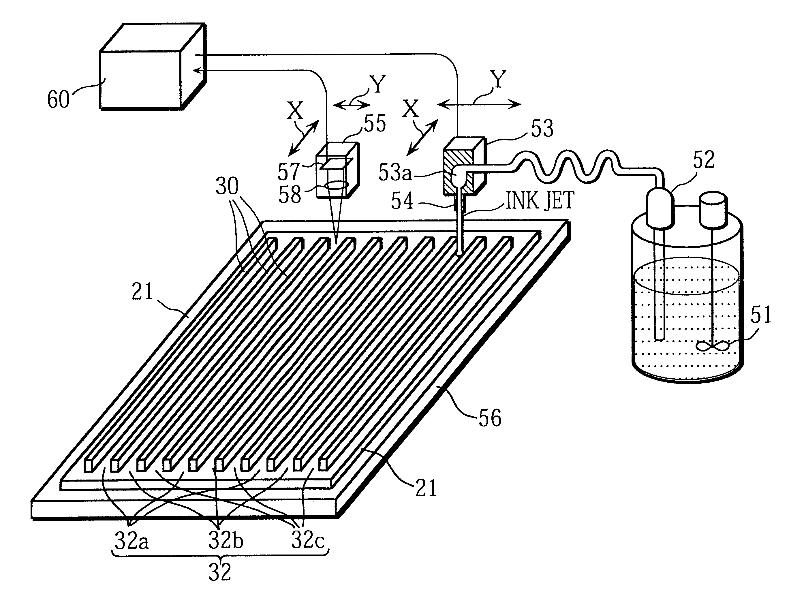
FIG. 12 is a perspective drawing of the ink application apparatus of the present embodiment, while FIG. 13 shows a frontal elevation (partially in cross-section) of this ink application apparatus.

This ink application apparatus has fundamentally the same construction as the ink application apparatus 50 described earlier, though it further includes other mechanisms, such as a circulating mechanism that collects and uses phosphor ink and a nozzle revolving mechanism that revolves a nozzle head including a plurality of nozzles to adjust the nozzle pitch.

Construction of the Ink Application Apparatus

The present ink application apparatus is composed of a main body 100 and a controller 200.

The main body 100 includes a main base 101, a rail 102 laid on the upper surface of the main base 101, a substrate mounting stand 103 that moves along the rail 102 in the X-axis (shown by the arrow X in the drawing), an arm 104 provided so as to cross the main base 101, a nozzle head unit 110 that moves i...

third embodiment

The ink application apparatus of the present embodiment is similar to the ink application apparatus of the second embodiment, but has a different circulating mechanism for circulating phosphor ink.

FIG. 18 shows the construction of the ink circulating mechanism in the ink application apparatus of the present embodiment.

Like the circulating mechanism 150 of the second embodiment, the circulating mechanism 160 collects phosphor ink that has been expelled by the nozzles 113 of the nozzle head 112 using a collecting vessel 151 and supplies the phosphor ink that has been collected back to the nozzle head 112. However, a disperser 161 is also provided on the supply route from the collecting vessel 151 to the nozzle head 112.

The disperser 161 is a sand mill in the form of a flow pipe that is filled with zirconia beads with a particle diameter of 2 mm or less. The rotation discs 163 spin at 500 rpm or below in a predetermined direction so that the beads stir the phosphor ink flowing inside t...


PUM


Abstract

The present invention intends to provide a manufacturing method for a PDP that can continuously apply phosphor ink for a long time and can accurately and evenly produce phosphor layers even when the cell construction is very fine. To do so, phosphor ink is continuously expelled from a nozzle while the nozzle moves relative to channels between partition walls formed on a plate so as to scan and apply phosphor ink to the channels. While doing so the path taken by the nozzle within each channel between a pair of partition walls is adjusted based on position information for the channel. When phosphor particles is successively applied to a plurality of channels, phosphor ink is continuously expelled from the nozzle even when the nozzle is positioned away from the channels. The phosphor ink is composed of: phosphor particles that have an average particle diameter of 0.5 to 5 mum; a mixed solvent in which materials selected from a group consisting of terpineol, butyl carbitol acetate, butyl carbitol, pentandiol, and limonene are mixed; and a binder that is an ethylene group polymer or ethyl cellulose containing at least 49% of ethoxy group (-OC2H5) cellulose molecules. After dispersion a charge-removing material is added to the phosphor ink.

Description

The present invention relates to a manufacturing method for a plasma display panel, and in particular to improvements to a phosphor ink used to form the phosphor layer and to a phosphor ink applying device.In recent years, there have been high expectations for the realization of large-screen televisions with superior picture quality. One example of such televisions are televisions for the "HiVision" standard used in Japan. In the field of display devices, research is being performed into a variety of devices, such as CRTs (Cathode Ray Tubes), LCDs (Liquid Crystal Displays), and Plasma Display Panels (hereafter PDPs) with the aim of producing suitable televisions.Cathode ray tubes that are conventionally used in televisions have superior resolution and picture quality. However, the depth and weight of CRT televisions increases with screen size, so that CRTs are not suited to the production of large televisions with screen sizes of forty inches or more. LCDs have some notable advantag...

Claims


Application Information

Patent Timeline
IPC IPC(8): H01J9/227H01J9/22H01J11/42
CPCH01J9/227H01J2211/42H01J9/22H01J11/42
Inventor KAWAMURA, HIROYUKISUZUKI, SHIGEOAOKI, MASAKIMIYASHITA, KANAKOOHTANI, MITSUHIROKADO, HIROYUKISUMIDA, KEISUKEKIRIHARA, NOBUYUKI
Owner PANASONIC CORP
Why Eureka
Try Eureka