Class D switching audio amplifier

a switching audio amplifier and amplifier technology, applied in the direction of amplifiers with modulator-demodulator, amplifiers with semiconductor devices/discharge tubes, dc amplifiers with negative-feedback circuit arrangements, etc., can solve the problems of wasting energy, existing class d amplifier designs suffer several disadvantages, modulation, isolation, feedback,

Inactive Publication Date: 2003-05-13
EVENSTAR MERGERSUB INC
View PDF4 Cites 73 Cited by
  • Summary
  • Abstract
  • Description
  • Claims
  • Application Information

AI Technical Summary

Problems solved by technology

Amplifier topologies that operate in a partially on state, such as Class A and AB, act like resistors and produce heat, thereby wasting energy.
Unfortunately, existing Class D amplifier designs suffer several disadvantages, including disadvantages related to modulation, isolation, feedback, and board layout.
Thus, a differential voltage is always present at the output causing power to be lost via the loudspeaker or low pass filter even in the absence of an audio input to the amplifier.
Existing Class D amplifiers typically require large power transformers to accommodate a relatively inefficient output stage and to meet government regulations requiring high voltage isolation between AC mains and all user-accessible inputs and outputs.
Unfortunately, such power transformers are large and expensive.
Unfortunately, these transformers suffer from limited frequency response, making implementation difficult.
Consequently, expensive heat-sinking is required, and large, expensive power transformers are needed to deliver 66% more power than the desired output power of the amplifier.
Unfortunately, expected theoretical efficiencies of 90+% for the Class D amplifier have not been achieved, due primarily to the many problems and disadvantages set forth herein.
Resistor tolerances greater than 1% in the differential amplifier and the RC low pass filter sections result in reduced common-mode rejection, potentially damaging voltages at the differential amplifier, and degraded product reliability.
This can result in decreased efficiency as power is lost in the RC low pass filter even in the absence of an audio input signal.
Unfortunately, precision matching and increased power handling requirements for the RC low pass filter resistors result in increased cost and size.
As a result, high power designs are required to incorporate expensive high power inductors that can dissipate the switching energy even when no audio input signal is present.
Existing Class D amplifiers typically exhibit high harmonic distortion above 1 kHz as a result of pulse transient damping issues and poor triangle waveform damping generation.
Excessive pulse undershoot and overshoot result from high inductance board layouts and power supplies.
Such undershoot and overshoot can degrade reliability for many standard FET driver ICs such as Harris' HIP4080A.
Additionally, pulse transient damping issues also lead to increased EMI emissions that increase the cost of shielding the amplifier.
Triangle waveform generation has always been a source of distortion in Class D amplifier designs.
These Class D amplifier designs suffer from high frequency noise superimposed on the triangle waveform; in turn, the high frequency noise results in increased harmonic distortion.
Thus, existing Class D amplifiers typically exhibit undesirable harmonic distortion much greater than 0.5%.
With prior art modulation schemes no advantage was gained from common-mode filtering because the output of the H-bridge was a differential voltage waveform.
As a result, high power designs were required to incorporate expensive high current, low resistance inductors in the LC low pass filters that could absorb the switching energy with or without an audio signal present.

Method used


Image

  • Class D switching audio amplifier
  • Class D switching audio amplifier
  • Class D switching audio amplifier

Examples


Embodiment Construction

, below.

A preferred embodiment of the present invention is described in detail below with reference to the attached drawing figures, wherein:

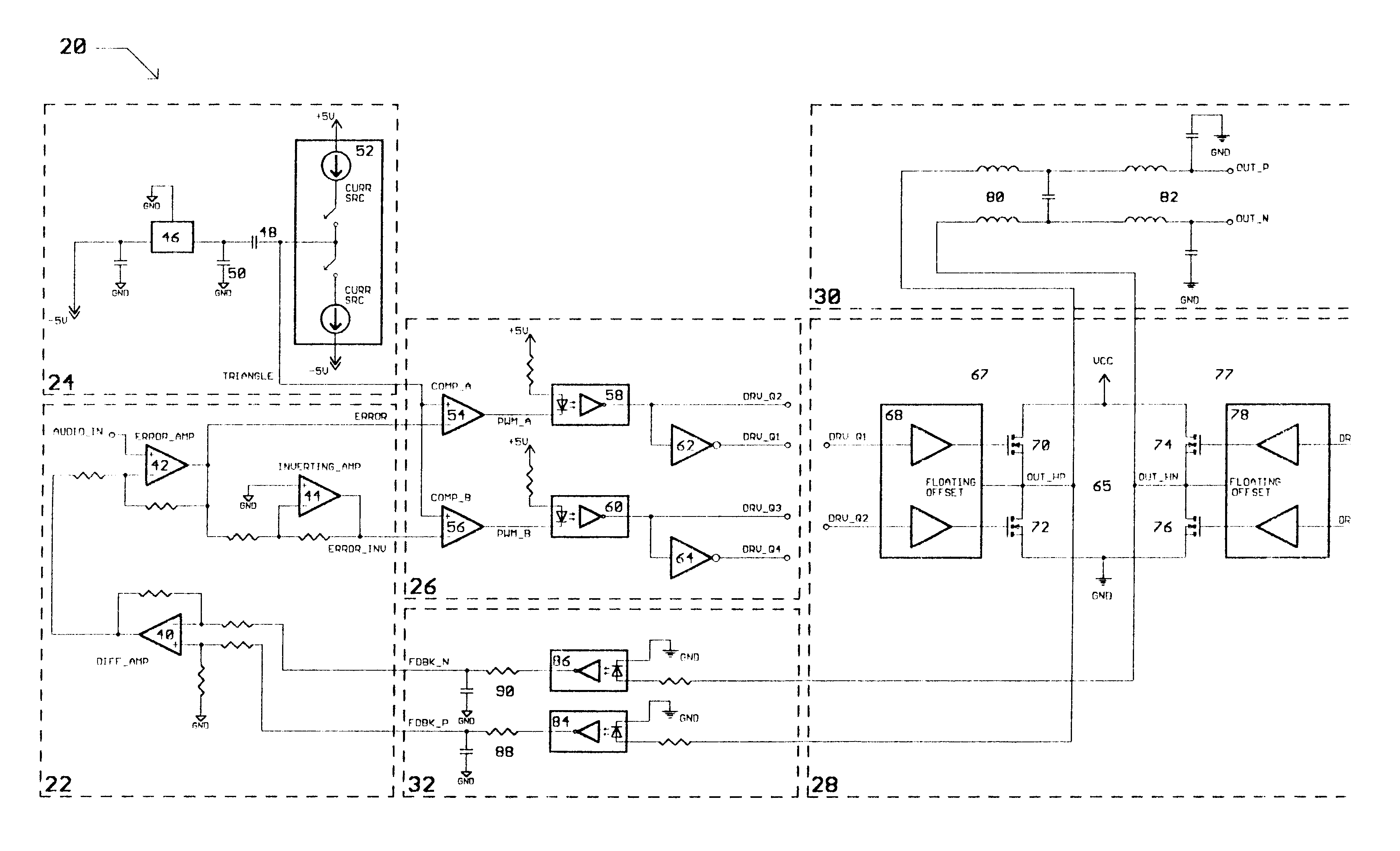
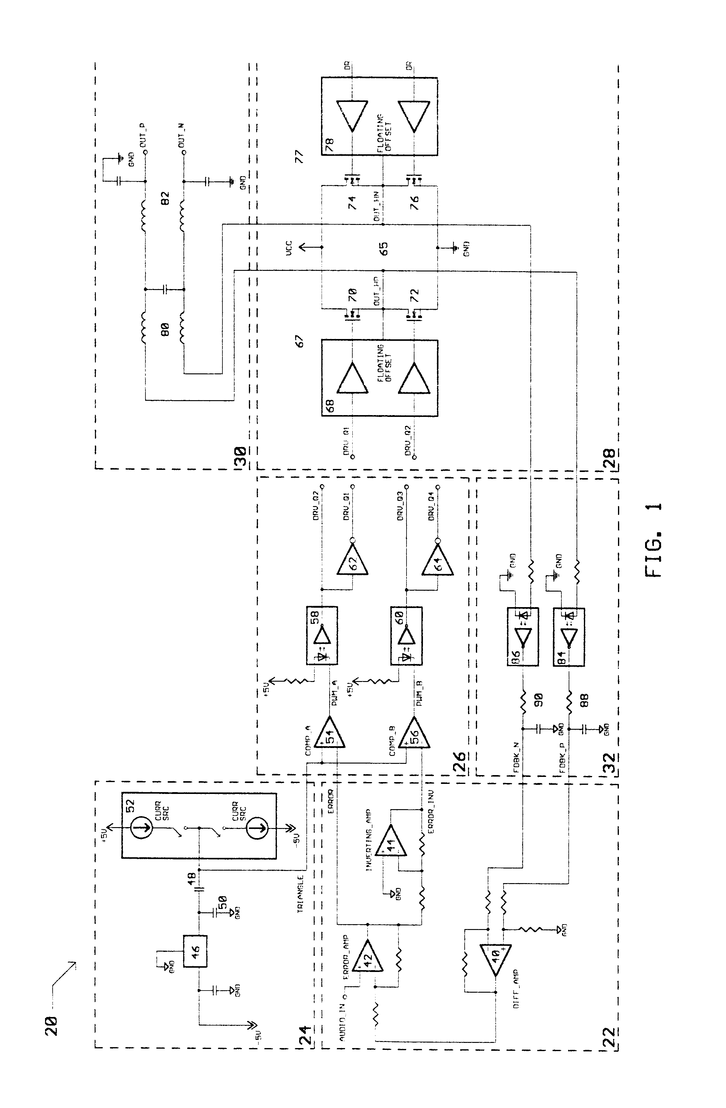
FIG. 1 is a circuit diagram of a preferred embodiment of the present invention;

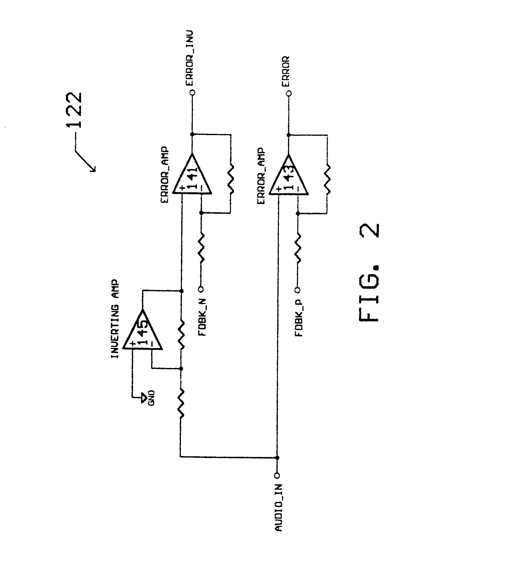
FIG. 2 is a circuit diagram of an alternate circuit topology for an input stage portion of the present invention;

FIG. 3 is a circuit diagram of an alternate circuit topology for a gate drive stage portion of the present invention;

FIG. 4 is a circuit diagram of a first alternate circuit topology for a feedback stage portion of the present invention;

FIG. 5 is a circuit diagram of a second alternate circuit topology for the feedback stage portion of the present invention;

FIG. 6 is a depiction of a switching portion of the output stage in a configuration corresponding to a first switch state;

FIG. 7 is a depiction of the switching portion of the output stage in a configuration corresponding to a second switch state;

FIG. 8 is a depiction of the switching portion of the out...


PUM


Abstract

A Class D switching audio amplifier incorporating four state modulation, input-to-output drive and feedback signal isolation, dual topology output filtration, and a low inductance board layout. The four state modulation results in a common mode voltage in the absence of audio. The input-to-output isolation of drive and feedback signals allows for elimination of large power transformers in applications without user-accessible outputs. Such isolation may make use of optical isolators. The output filter includes common mode and differential topology filter stages. The low inductance board layout treats the amplifier and power supply boards as modules, and utilizes both sides of the amplifier board in order to minimize trace length.

Description

1. Field of the InventionThe present invention relates to Class D switching audio amplifiers. More particularly, the present invention relates to a Class D switching audio amplifier making use of four state modulation, input-to-output drive and feedback signal isolation, a dual topology output filter, and a low inductance board layout.2. Description of the Prior ArtIt is often desirable to amplify audio signals using a Class D switching audio amplifier. Basic circuit layout of the Class D amplifier is substantially similar to that of linear amplifiers, such as Class A, B, and AB, with a major difference being in the signals provided to an output stage. Rather than feeding an audio waveform directly to the output stage, as is done in linear amplifiers, the Class D amplifier first feeds the audio waveform into a Pulse Width Modulator (PWM) circuit which feeds modulated pulses to the output stage. By quickly switching the output stage completely on and completely off with varying pulse...

Claims


Application Information

Patent Timeline
Patent Type & Authority Patents(United States)
IPC IPC(8): H03F3/38H03F3/217H03F3/20
CPCH03F3/217H03F3/2171H03F3/085H03F3/38H03F3/2173
Inventor BUTLER, JOEL
Owner EVENSTAR MERGERSUB INC
Why Eureka
Try Eureka