However, with increasing costs of hospital stays and increased awareness by patients of other minimally invasive
surgical procedures, interest in developing a minimally invasive CABG procedure is increasing.
After twenty to thirty minutes of
ischemia, irreparable damage may occur and no matter how good the repair, the heart function may be inadequate to allow the patient to survive.
An unforeseen consequence of these technology developments was the decline in interest in technology to facilitate and expedite heart
surgery.
Therefore, while the art in the 1960's and 1970's contained numerous examples of devices intended to expedite heart-related surgery, the incidence of such devices declined after about 1970.
Although this procedure is currently well perfected, the patient suffers intense pain and generally requires a long
recovery period.
Furthermore, the interest in
less invasive surgical approaches is promoting concomitant interest in many areas that were abandoned long ago, including coronary fastening and
valve replacement.
However, since use of cardioplegia requires additional support and expense during the anastomosis procedure, the inventors believe that it is best to attempt to fasten the anastomosis while the heart is beating.
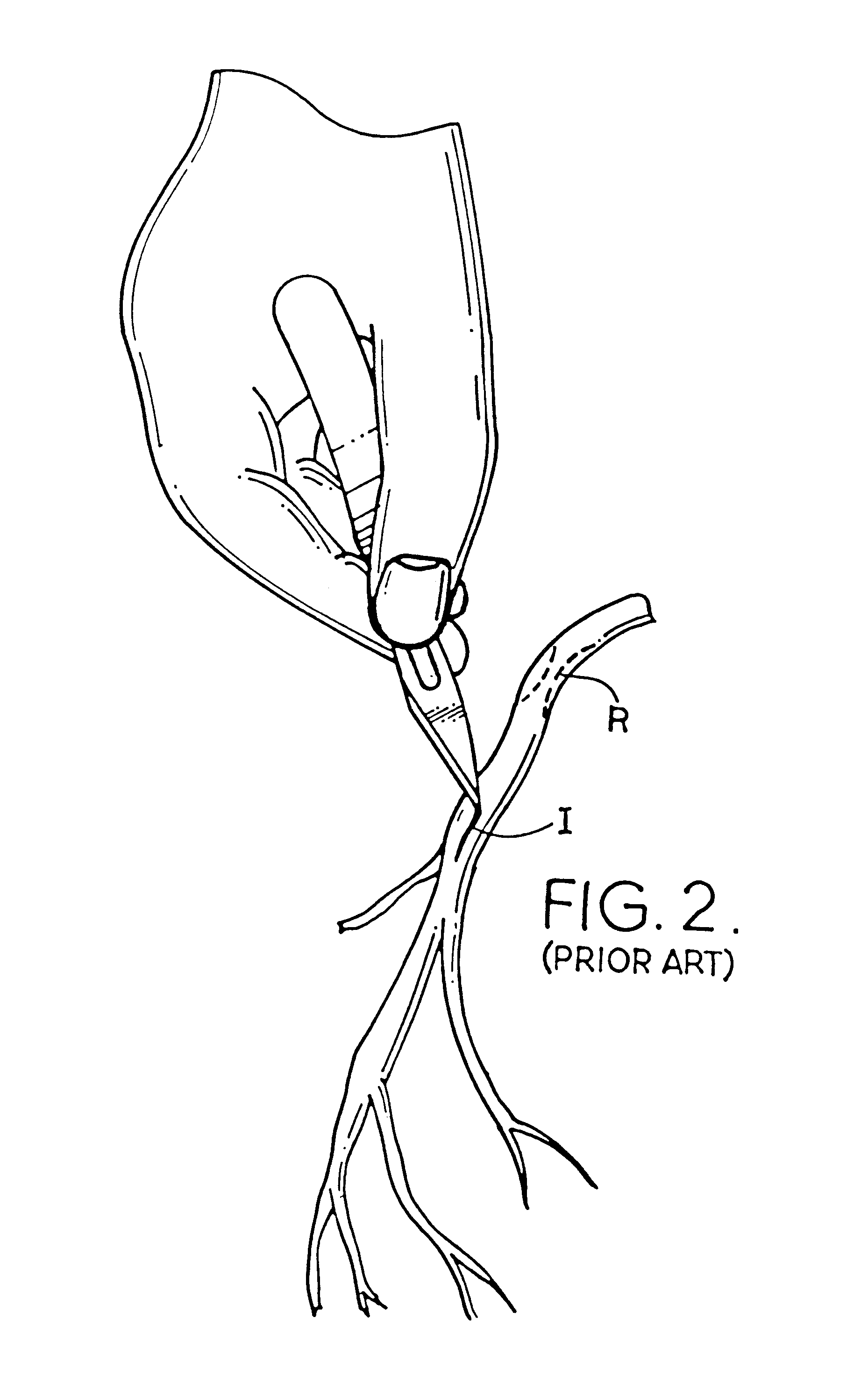
However, this procedure when performed with a hand suturing technique is very imprecise due to the translation of movement from the
beating heart to the suspended
artery.
Imprecise placementof the sutures may cause a
distortion of the anastomosis which may cause
stenosis at the junction.
As one can imagine it is difficult enough to place
suture needles the size of a small
eyelash into a vessel wall with placement accuracy of better than 1 mm; yet to accomplish this feat of precision on a moving target is even more difficult.
On a
beating heart it may be difficult to place the sutures with the position precision required.
However, it is impossible to isolate all movement of the vessel during an anastomosis procedure.
Methods that attempt to stabilize and isolate an artery from the movement of the
beating heart may damage the vessel or cause myocardial injury (MI).
In addition to the problem of accurately placing sutures, an incision through the artery wall to open the artery must be made.
This, too, is a delicate procedure even on a still heart because the incision must be of a precise length.
It is also critical to not penetrate the back wall or side wall of the vessel which will lead to complications.
Without cardioplegia,
blood flow to the heart
muscle must also be provided while the heart is beating; therefore, after the initial
arteriotomy the surgical field is very bloody and obscured.
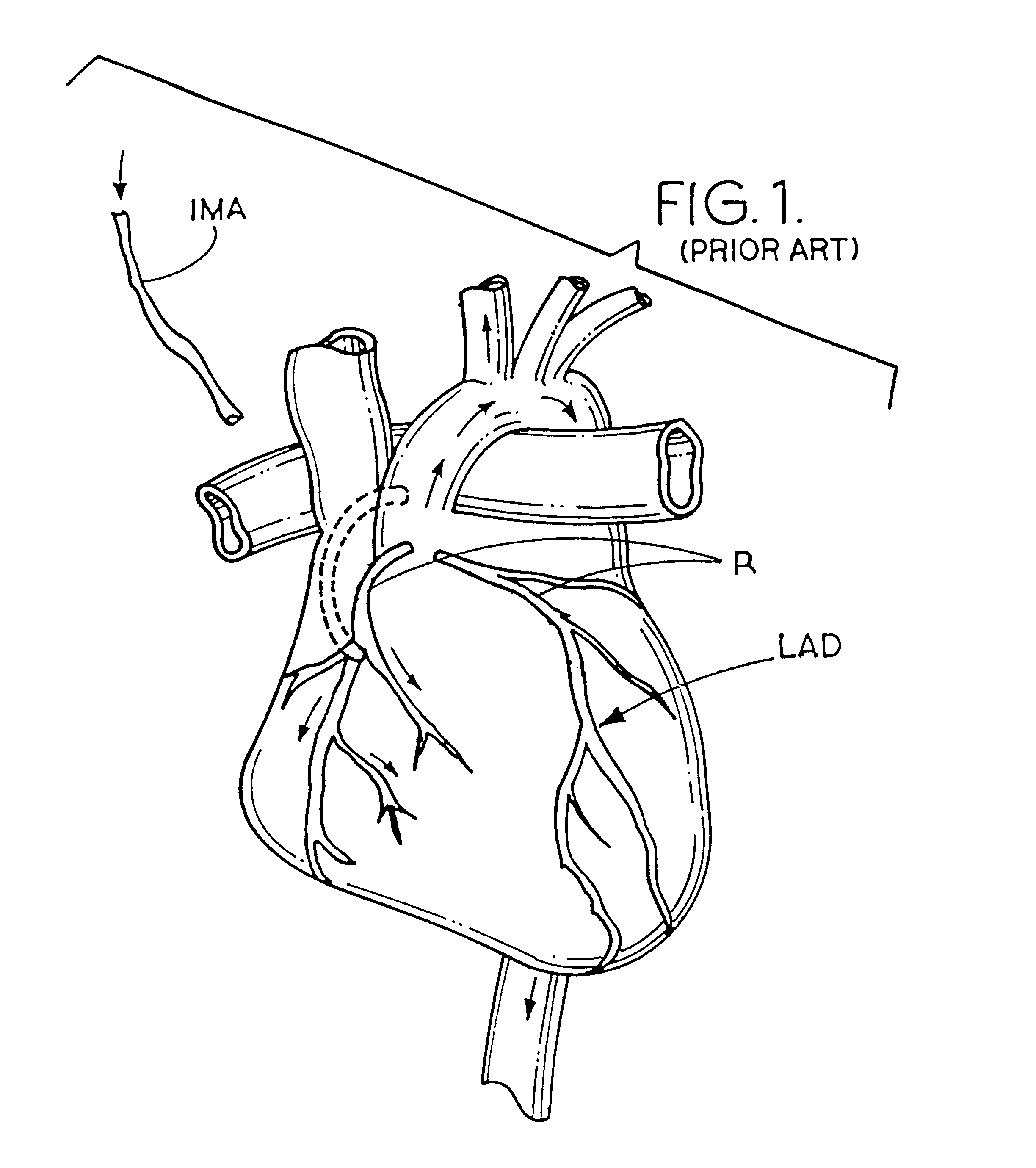
Access to the heart vessels other than the LAD will be extremely difficult with minimally invasive hand suturing due to the
anatomical location of the
posterior wall of the heart.
Although minimally invasive CABG procedures are taking place now with sutured anastomosis they require superlative skills and are therefore not widely practiced.
One of the most vexing problems is that of adequate access.
If special tools are constructed to allow the surgeon to hold
suture needles on the end of a long instrument, the added length of the tool only amplifies any inaccurate manipulation.
If the sutures are not correctly placed in the vessel walls, bunching or leaks may occur.
In the minimally
invasive procedure this is disastrous usually resulting in the conversion to an open chest procedure to correct the mistake.
Any rough handling of the vessel walls is detrimental as
inflammation can cause further postoperative complications.
While the art contains disclosures of several devices that are used to join blood vessels, these devices are primarily directed to an end-to-end anastomosis, and thus are inadequate for CABG procedures.
Furthermore, the techniques taught in the prior art often require the vessels to be severely deformed during the procedure.
Pulling or stretching the vessel walls produces a very unpleasant and unexpected result.
Therefore, the tissue will not stretch as easily in the radial or circumferential direction and results in a narrowing or restriction when pulled or stretched in the prior art devices.
Such manhandling will result in restrictions and stenotic junctions because the vessel walls will react poorly to being treated in such a rough manner and the stretching of the vessel wall will telegraph up the vessel wall due to the high radial stiffness of the
vessel structure causing restrictions and spasms in the vessel wall.
The prior art fails to teach that the vessels are living tissue and must not be made to conform to rigid fitting-like shapes.
Additionally, the prior art fails to teach methods of ensuring
hemostasis so there is no leakage under pressure.
It is noted that
mechanical devices used to join blood vessels are extremely difficult to seal.
A knot that is too loose may cause the wound to leak and have trouble healing causing excessive
scar tissue to form.
A knot that is too tight may tear through the delicate tissue at the suture hole causing leaks.
It is further noted that the junctions taught in the prior art are not anatomically correct both for
blood flow and for healing.
The prior art junctions do not account for such flow characteristics and parameters and are thus deficient.
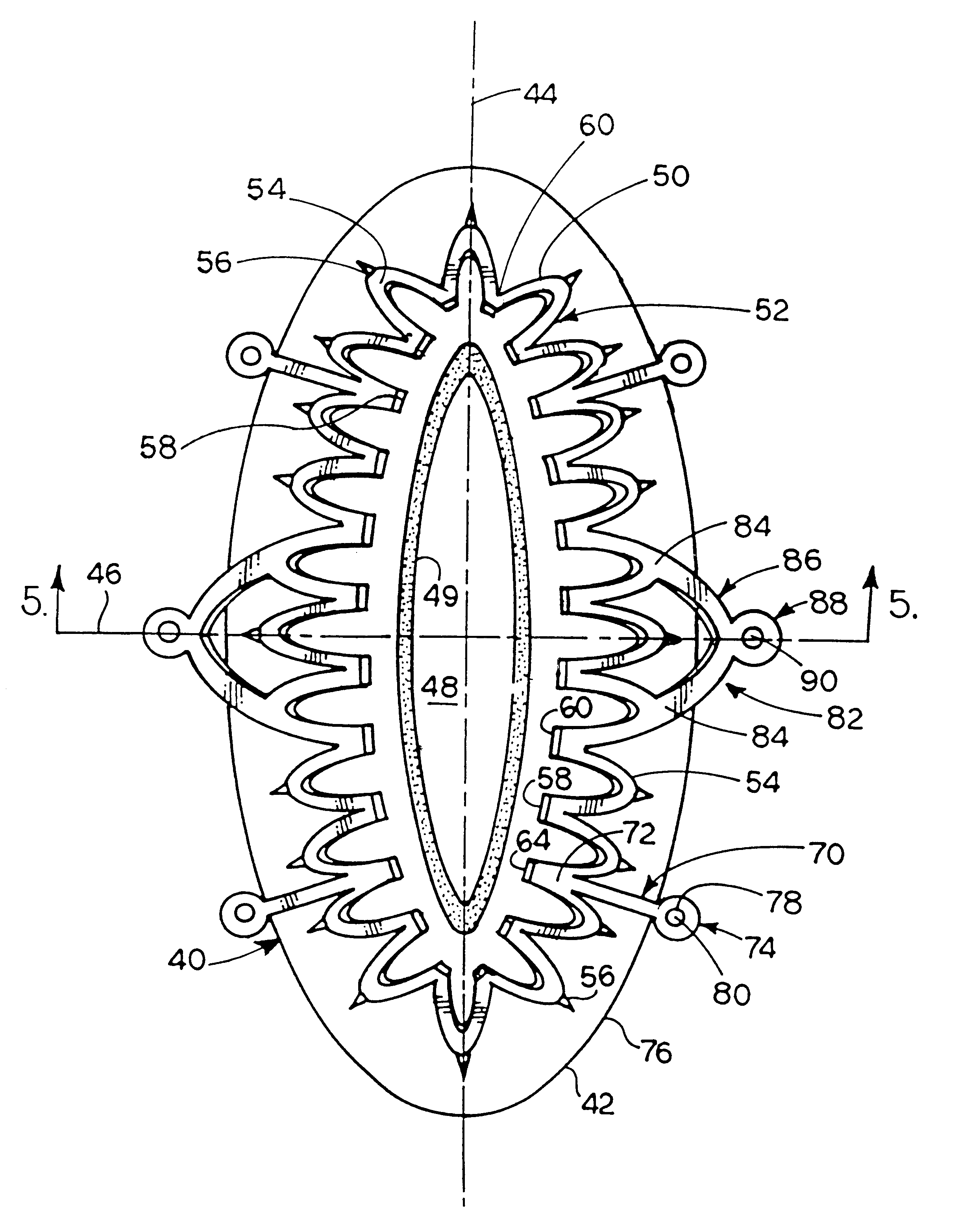
With a rigid ring that has a singular circular cross section of the graft, the fitting does not allow the vessel to provide this increase in flow as the vessels expand to meet the needs of the heart
muscle.
If the incised edges are too far apart scarring will occur causing restrictions.
The walls cannot be compressed between two hard surfaces which will damage the vessels.
However, clamping and compressing the vessel walls too tightly may cause
necrosis of the vessel between the clamps.
If
necrosis occurs the dead tissue will become weak and most likely cause a failure of the joint.
Still further such rings and tubes used to clamp vessels together do not follow the correct anatomical contours to create an unrestricted anastomosis.
Failing to account for the way healing of this type of junction occurs and not accounting for the actual situation may cause a poor result.
In a mechanical minimally invasive
system it will not be possible to put an "extra suture throw" in so the
system must provide a way to assure complete
hemostasis.
And since the design errs on the side of not over-compressing the tissue there may be very small areas that may present a leak between the edges of the vessel walls.
Accordingly healing with prior art techniques using mechanical joining means is not as efficient as it could be.
Large breaks in vessel walls which are under pressure cannot be effectively sealed by platelets and
fibrin without a substrate to collect on.
Still further, some vessels are located or sized in a manner that makes placing elements thereon difficult.
This saves time and resources and may be necessary if only short sections or a limited amount of host graft material is available.
At the present time, existing means and methods of performing an anastomosis do not permit the formation of multiple anastomotic sites on a single graft vessel at both proximal and distal ends.
This will be either impossible or very expensive.
This is still achieved in a minimally
invasive surgery situation where proper control of the incised vessels can be difficult to achieve, especially when the patient's heart is beating during the procedure, and. does not require a hemostatic medium.
Still further, the procedure will be performed in a very difficult
sight area.
These two situations combine to make proper alignment of the vessels extremely difficult.
These conflicting considerations present a significant problem.
While it might appear to be best to clamp the joint tightly together to prevent leaks, too much force clamping the tissue is not desirable because the
tissue healing response is altered by crushing forces.
If applied to the malleable stents of interest, it would round the fasteners in an acceptable manner but the tips of the tines would become dull and, unable to pierce the vessel wall and the malleable
stent would become too weak from the amount of material which has been removed.
Also, the malleable
stent would not be perfectly planar due to the inconsistent nature of
electropolishing.
The problem with this process is the parts must be stiff enough to withstand the tumbling effect, and not be bent or deformed by the process.
Also parts such as those of interest may tangle with each other when removed making it difficult to separate the parts without damage thereto.
Furthermore this type of deburring is not a precision operation.
Thus, for the product of interest, some tines may be sharper or thinner than others thereby adversely affecting not only the ability of the joint to be leak-free but also compromising the deployment of the malleable stent on the vessel.
However, the parts may be inconsistent.
While the anastomotic joint is usually created oversized to accommodate this demand it is difficult to predict the exact size that will be needed years ahead.

