
Output buffer having a plurality of switching devices being turned on successively at shorter time intervals to achieve increasing drive capability using a predriver

Inactive Publication Date: 2003-06-10
SEIKO EPSON CORP
View PDF9 Cites 19 Cited by
  • Summary
  • Abstract
  • Description
  • Claims
  • Application Information

AI Technical Summary

Problems solved by technology

The output buffer circuit shown in FIG. 14 requires high precision in the resistors R1 and R2 and the capacitor C. Therefore, it is difficult to form the output buffer circuit by gate arrays, and conventionally, a custom design is required to realize an output buffer circuit.
Further, circuit tuning of the output buffer circuit shown in FIG. 14 is difficult.
Accordingly, conventional output buffer circuits that achieve the low data transfer speed of the USB require a great number of process steps and costs.
When six or more switching circuits are used, it is difficult to achieve the time shorter than the upper limit of 300 ns.

Method used


Image

  • Output buffer having a plurality of switching devices being turned on successively at shorter time intervals to achieve increasing drive capability using a predriver
  • Output buffer having a plurality of switching devices being turned on successively at shorter time intervals to achieve increasing drive capability using a predriver
  • Output buffer having a plurality of switching devices being turned on successively at shorter time intervals to achieve increasing drive capability using a predriver

Examples


third embodiment

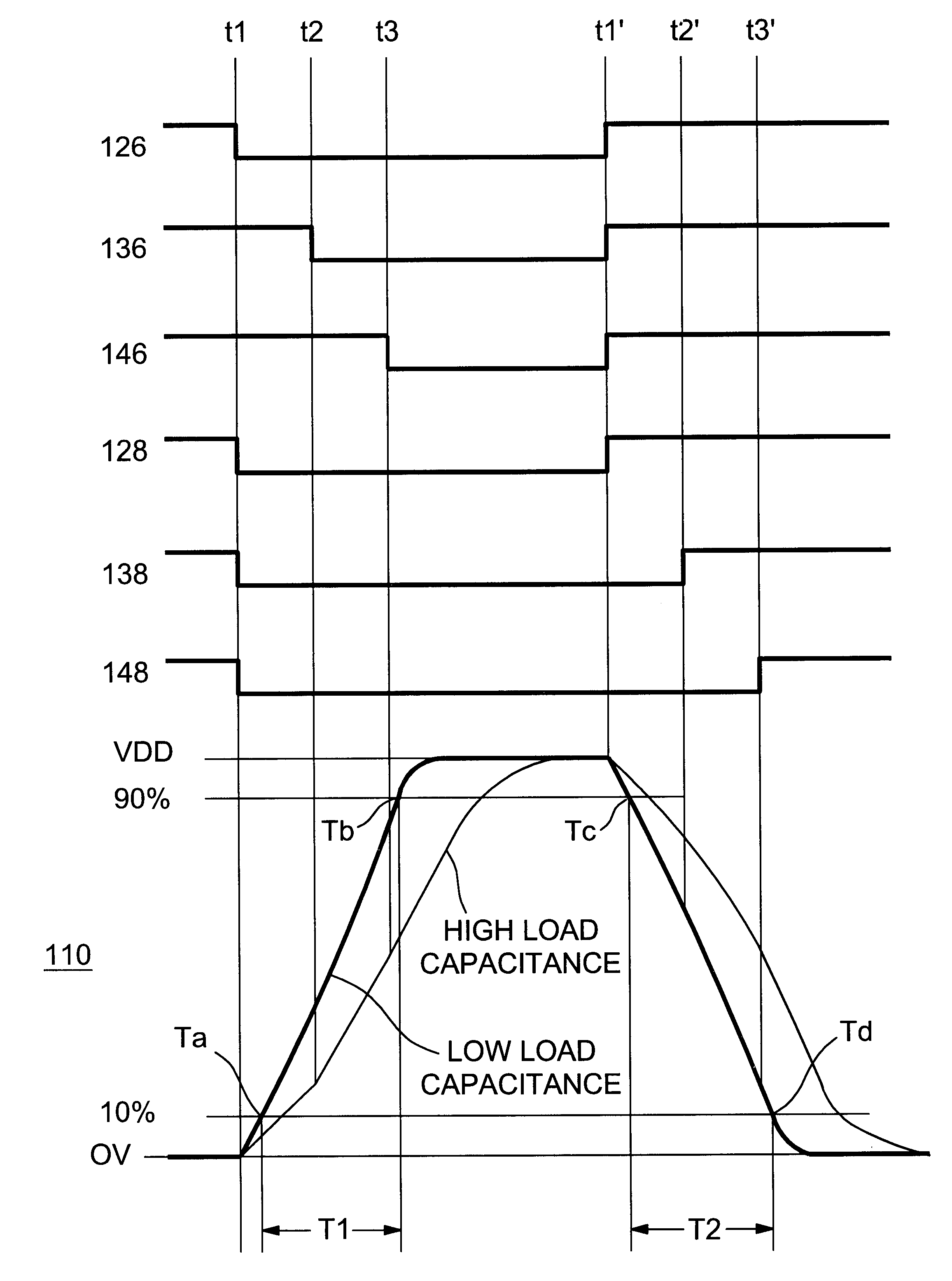
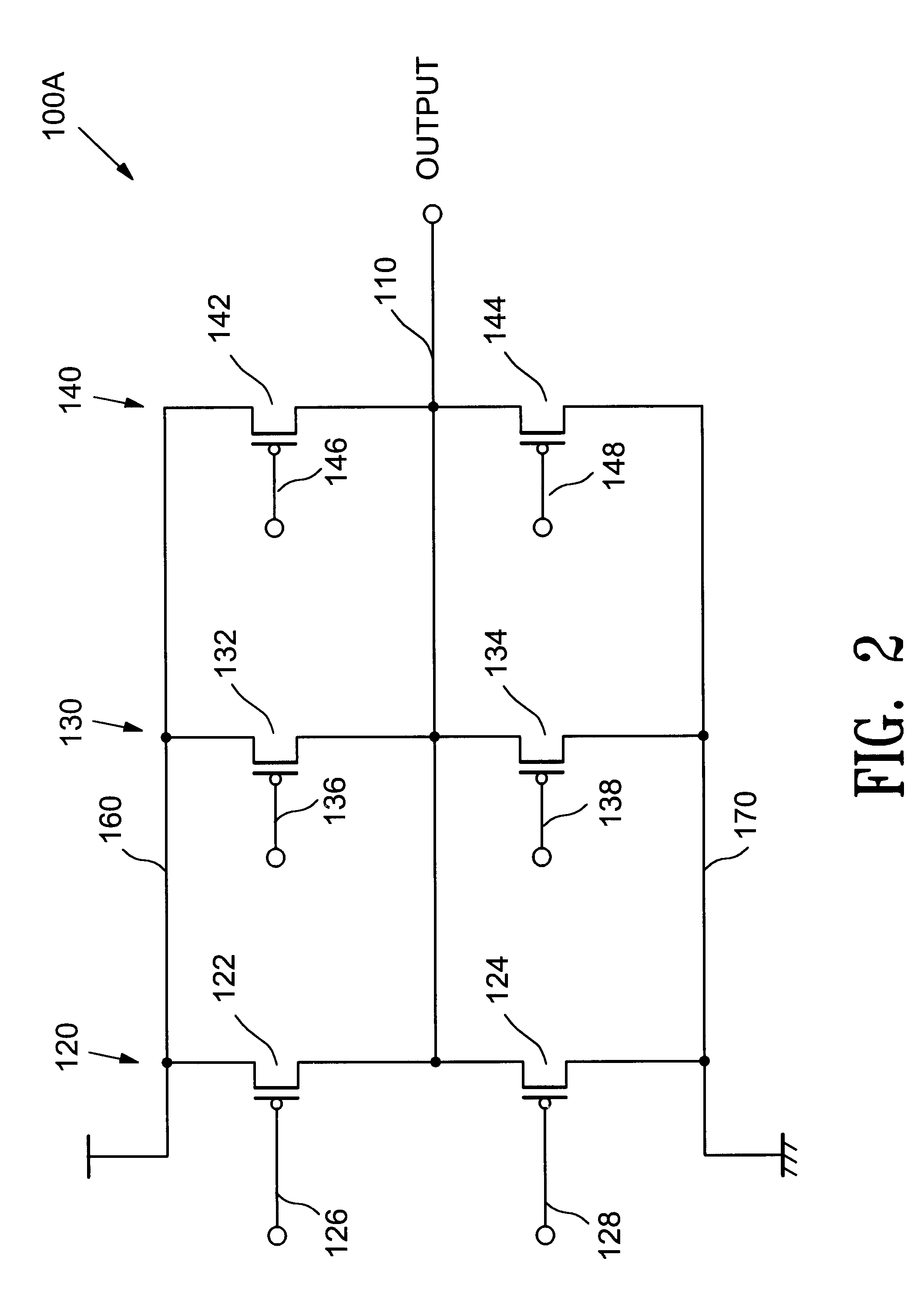
FIG. 6 shows an output drive circuit 100B, in accordance with the present invention, that is provided in an output buffer circuit (including an output buffer circuit in an input / output buffer circuit) that performs a low speed data transmission in the devices shown in FIG. 1. The output drive circuit 100B shown in FIG. 6 includes a fourth switching circuit 150, in addition to the first, the second and the third switching circuits 120, 130 and 140 shown in FIG. 2. The fourth switching circuit 150 is also made up of a CMOS transistor. The CMOS transistor has a first switching device and a second switching device, namely, a P-type MOS transistor 152 and an N-type MOS transistor 154, respectively. Gates of the P-type MOS transistor 152 and the N-type MOS transistor 154 connect to control signal lines 156 and 158, respectively, that independently turn the respective transistors on and off.

When the P-type MOS transistors 122, 132, 142 and 152 have current drivabilities, P1, P2, P3 and P4,...

fourth embodiment

In accordance with the present invention, the CMOS transistors in the first through the fourth switching circuits 120, 130, 140 and 150 shown in FIG. 6 are modified. FIG. 7 shows an output drive circuit 100C in which the modification is implemented. Referring to FIG. 7, a signal output line 110 of the output drive circuit 100C connects to an input / output signal line 182 that connects to an input / output terminal 180, and to an input signal line 186 that connects to a logic circuit 184 through an input buffer circuit 183. When the enable signal 216 becomes non-active and the output signal line 110 is placed in high impedance, a signal that is inputted through the input / output terminal 180 is supplied to the logic circuit 184 through the input buffer circuit 183.

Referring to FIG. 7, among first switching devices 122, 132, 142 and 152 and second switching devices 124, 134, 144 and 154 in the first through fourth switching circuits 120, 130, 140 and 150, some of them are composed of a pl...

sixth embodiment

FIG. 11 shows a master slice type semiconductor device (gate array) 300, in accordance with the present invention, with which any of the output buffer circuits in accordance with the embodiments described above. The semiconductor device 300 has an input / output circuit region 302 provided in a peripheral region and a logic circuit region 304 provided in a central region thereof.

The semiconductor device 300 is manufactured from a master slice. The master slice has plural pre-formed MOS transistors of different sizes, for example, with different gate widths of 3, 5, 10, 90 .mu.m. The transistors are wired with one another and a power source is wired according to the user's specification to complete the semiconductor device 300.

The input / output circuit region 302 includes at least an output buffer circuit in accordance with any one of the above-described embodiments. The output buffer circuit can be formed by wiring transistors of different sizes that are pre-formed on a master slice an...


PUM


Abstract

An output drive circuit of an output buffer circuit has a signal output line and first, second and third switching circuits connected to the signal output line at different locations thereof. Each of the first, second and third switching circuits includes one of first switching devices connected between a power source line and the signal output line, and one of second switching devices connected between the signal output line and a ground line. Each of the first, second and third switching circuits includes one of first control signal lines that turn on and off the first switching devices, respectively, and one of second control signal lines that turn on and off the second switching devices, respectively. Drivabilities of the first and / or the second switching devices in the switching circuits are set to gradually increase in a specified order.

Description

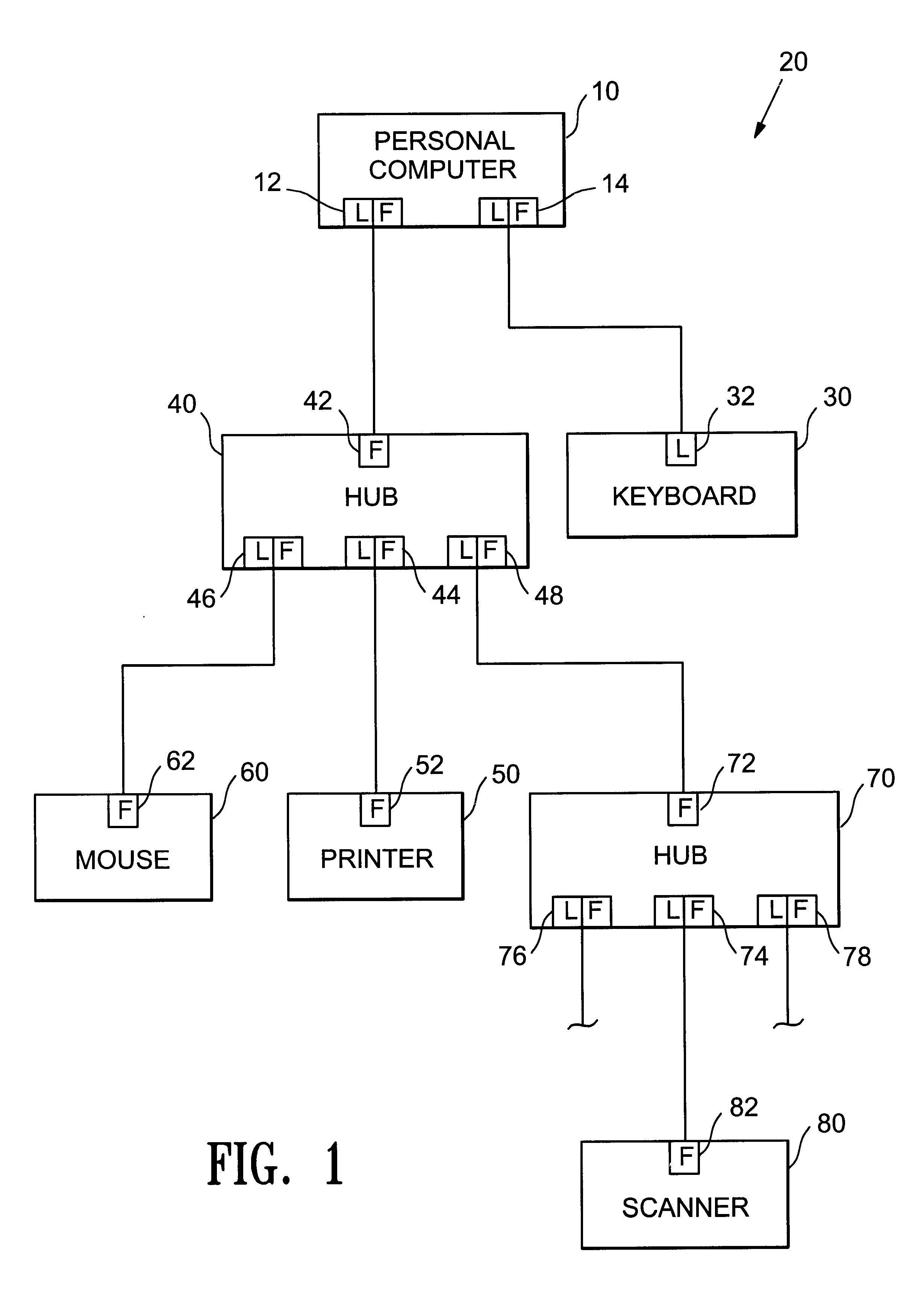
1. Field of the InventionThe present invention relates to an output buffer circuit that is suitable for outputting a signal at a low transfer speed, and a master slice type semiconductor device and an electronic apparatus using the output buffer circuit.2. Description of Related ArtUniversal Serial Bus (USB) is a known standard for connecting a personal computer to peripherals. Details of the standard are described in the Universal Serial Bus Specification Revision 1.0.The USB standard specifies two different data transfer speeds, namely, a full speed (at 12 Mbps) and a low speed (at 1.5 Mbps). The USB standard also specifies electrical characteristics required by an output buffer circuit for low speed, in which the rise time and the fall time of the waveform of an output are specified to be within a range of 75-300 ns for a wide range of load capacitances ranging from 50 to 350 pf.Conventionally, an output buffer circuit that realizes the low transmission speed of the USB is compos...

Claims


Application Information

Patent Timeline
IPC IPC(8): H03K17/16H03K19/0175
CPCH03K17/167H03K17/164
Inventor SUGITA, NATSUKI
Owner SEIKO EPSON CORP
Learn More